Wireless charging device

Inactive Publication Date: 2013-11-14
KIMREE HI TECH
View PDF6 Cites 68 Cited by
  • Summary
  • Abstract
  • Description
  • Claims
  • Application Information

AI Technical Summary

Benefits of technology

[0013]According to the present invention, a current limiting resistance and a compensation capacitor are applied based on traditional transmitting circuit. An insert total electromagnetic coupling structure and an insert detection are applied, which is particularly suitable for electronic cigarette. Compared to those in the pr

Problems solved by technology

Because a high heat value can be generated on the electronic switch due to a dynamic resistance, heat sinks with large area are needed to regulate the work of the electronic switch, which increases the cost and is especially adverse to prod

Method used


Image

  • Wireless charging device
  • Wireless charging device
  • Wireless charging device

Examples


Embodiment Construction

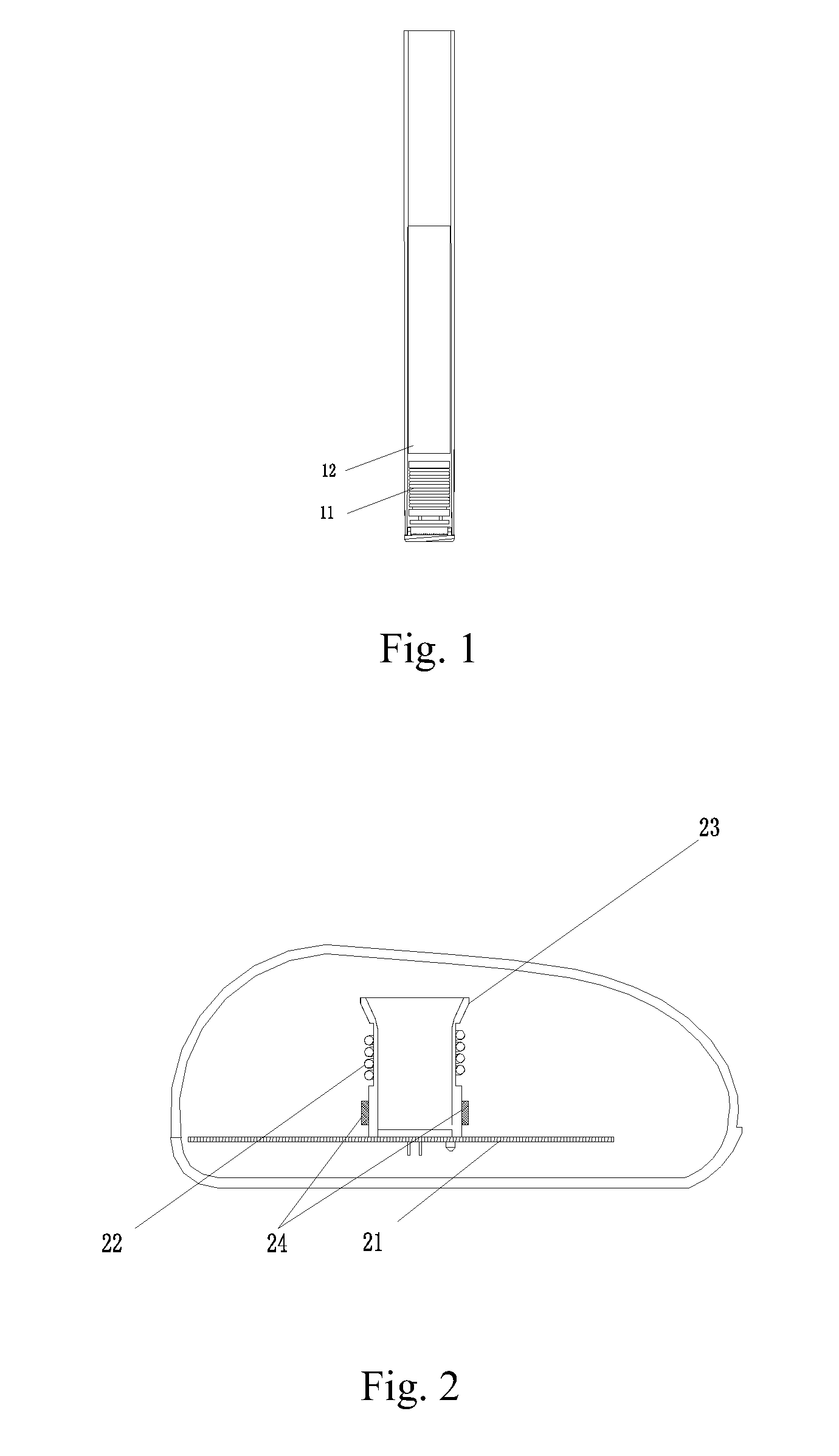
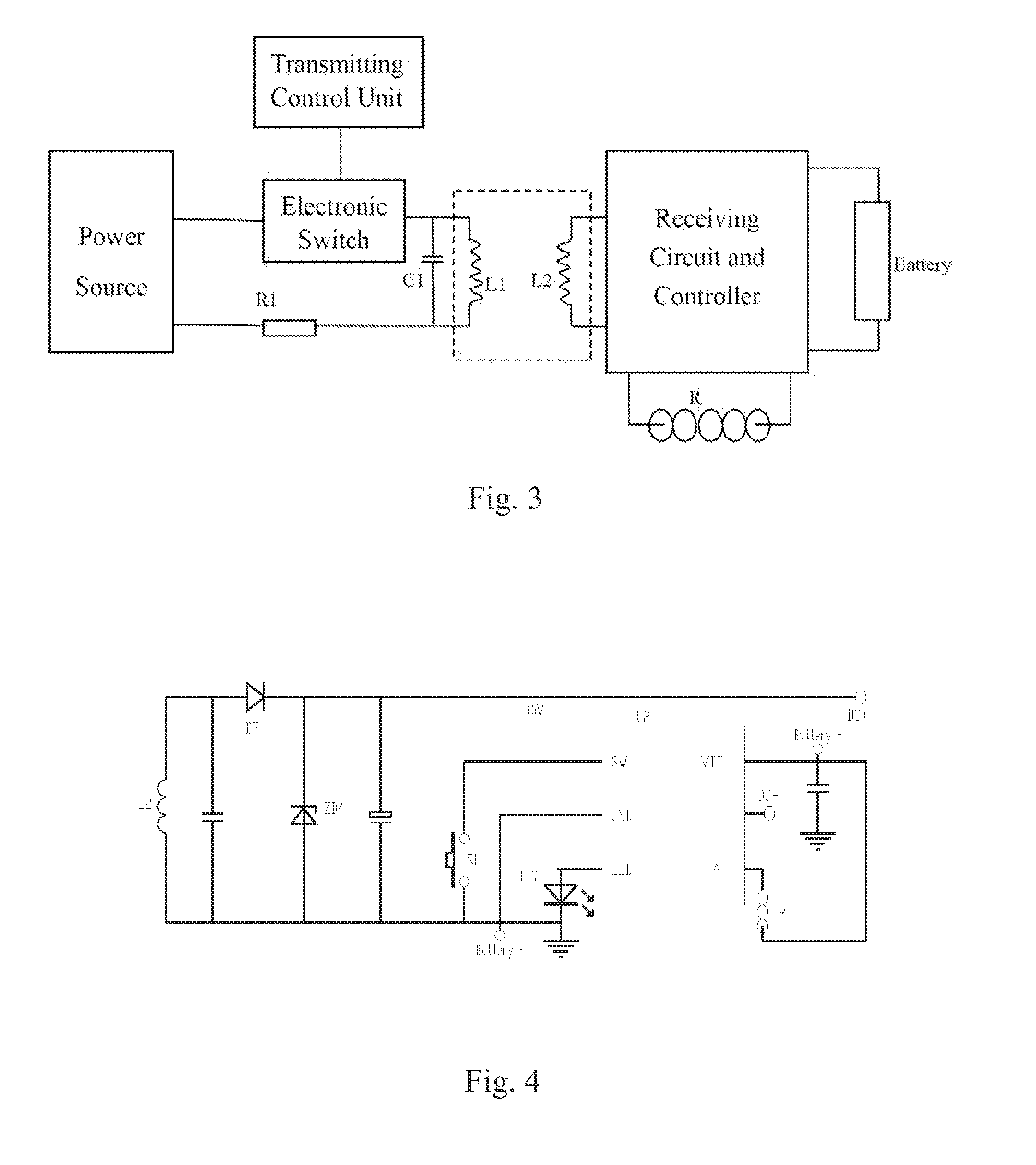
[0019]As shown in FIG. 1, an electronic cigarette according to the present invention is provided, comprising a battery 12 installed on the body of the electronic cigarette, and a receiving coil 11 provided on the head part of the electronic cigarette located in front of the battery 12. The receiving coil 11 is also labeled as L2 in FIG. 3 and FIG. 4.

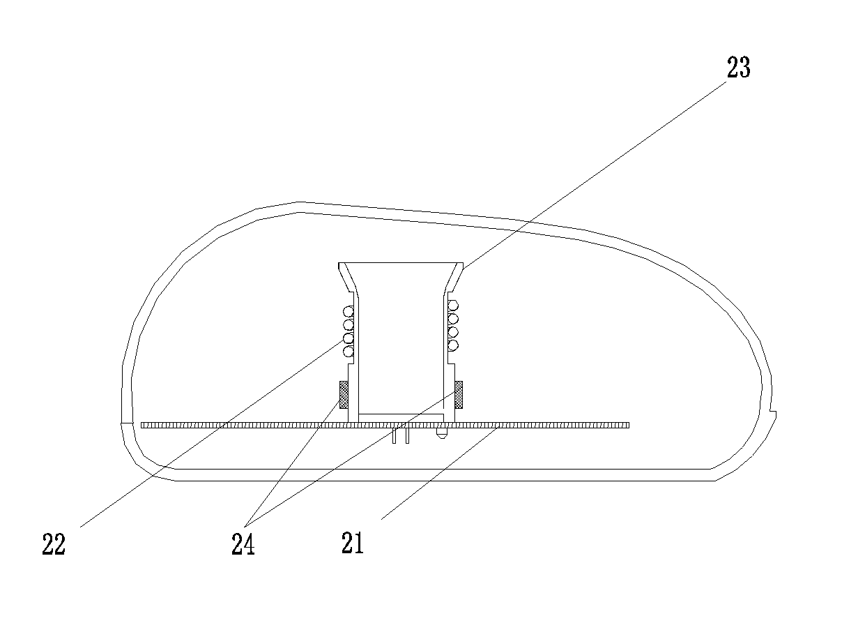
[0020]As shown in FIG. 2, a wireless charging device for the electronic cigarette according to the present invention is provided, comprising a circuit board 21, a sleeve 23, a photo detector 24 for testing the insertion of the electronic cigarette, and a transmitting coil 22. The transmitting coil 22 is also labeled as L1 in FIG. 3 and FIG. 5. The transmitting coil 22 is wrapped outside the sleeve 23, corresponding to the position for inserting the receiving coil 11 of the electronic cigarette. When the electronic cigarette is installed, the receiving coil 11 is inside the transmitting coil 22 with the axes of the two coils in the same d...


PUM


Abstract

A wireless charging device comprises an electronic switch and a transmitting coil (L1) electrically connected with a power source in sequence. A control end of the electronic switch is connected with a transmitting control unit. The wireless charging device further comprises a current limiting resistance (R1) connected in serial with the transmitting coil. The wireless charging device further comprises a compensation capacitor (C1) connected in parallel with the transmitting coil. An insert total electromagnetic coupling structure is further employed for charging. Such wireless charging device is particularly suitable for electronic cigarette, with low cost, stable and reliable working status and high efficiency, and specific heat sink is not required.

Description

FIELD OF THE PRESENT INVENTION[0001]The present invention relates to wireless charging technique, more particularly to a wireless charging device with low cost and high efficiency, especially be suitable for electronic cigarette.BACKGROUND OF THE PRESENT INVENTION[0002]At present, a wireless charging device comprises a power source, an electronic switch, and a transmitting coil electrically connected in sequence. Switch on / off of the electronic switch is controlled by a Pulse Width Modulation (PWM) controller. The transmitting coil is connected to the power source through the electronic switch. A field-effect switching tube with high power usually serves as the electronic switch mentioned above. Because a high heat value can be generated on the electronic switch due to a dynamic resistance, heat sinks with large area are needed to regulate the work of the electronic switch, which increases the cost and is especially adverse to product with low cost and small size. According to a tra...

Claims


Application Information

Patent Timeline
IPC IPC(8): A24F47/00H02J7/02A24F40/90
CPCA24F47/002H02J7/025H02J50/10H02J7/00304H02J7/0044A24F40/90H02J7/00309H02J50/12
Inventor XIANG, ZHIYONG
Owner KIMREE HI TECH
Why Eureka
Try Eureka