Current Sensing Module and Assembly Method Thereof

a current sensing module and current sensing technology, applied in the field of electric power distribution, can solve the problems of increasing the cost associated with the installation process, space consuming methods, and space consuming cts

Inactive Publication Date: 2008-04-03
GENERAL ELECTRIC CO
View PDF40 Cites 69 Cited by
  • Summary
  • Abstract
  • Description
  • Claims
  • Application Information

AI Technical Summary

Problems solved by technology

These CTs are space consuming and difficult to mount.
The installation of these CTs and the extensive internal wiring is a cumbersome, time-consuming process and therefore increa

Method used


Image

  • Current Sensing Module and Assembly Method Thereof
  • Current Sensing Module and Assembly Method Thereof
  • Current Sensing Module and Assembly Method Thereof

Examples


Embodiment Construction

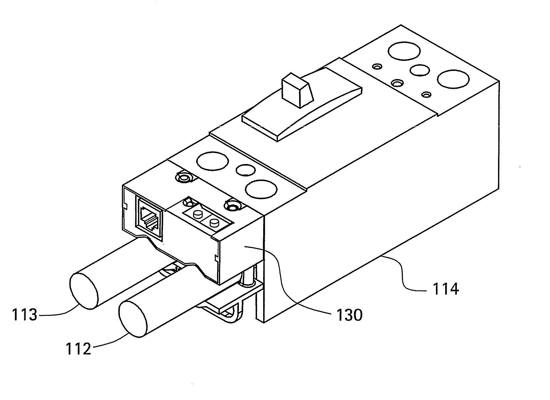
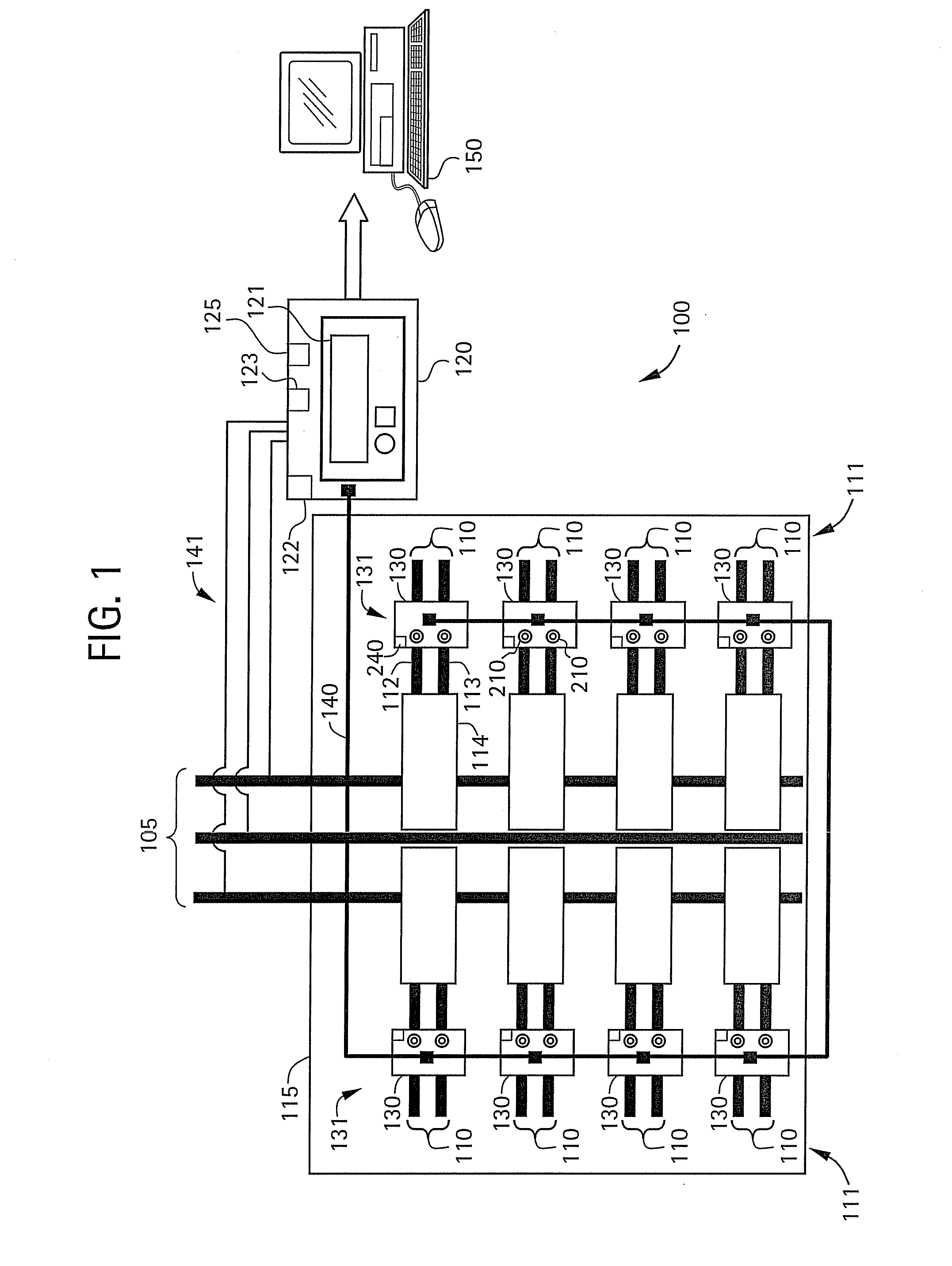
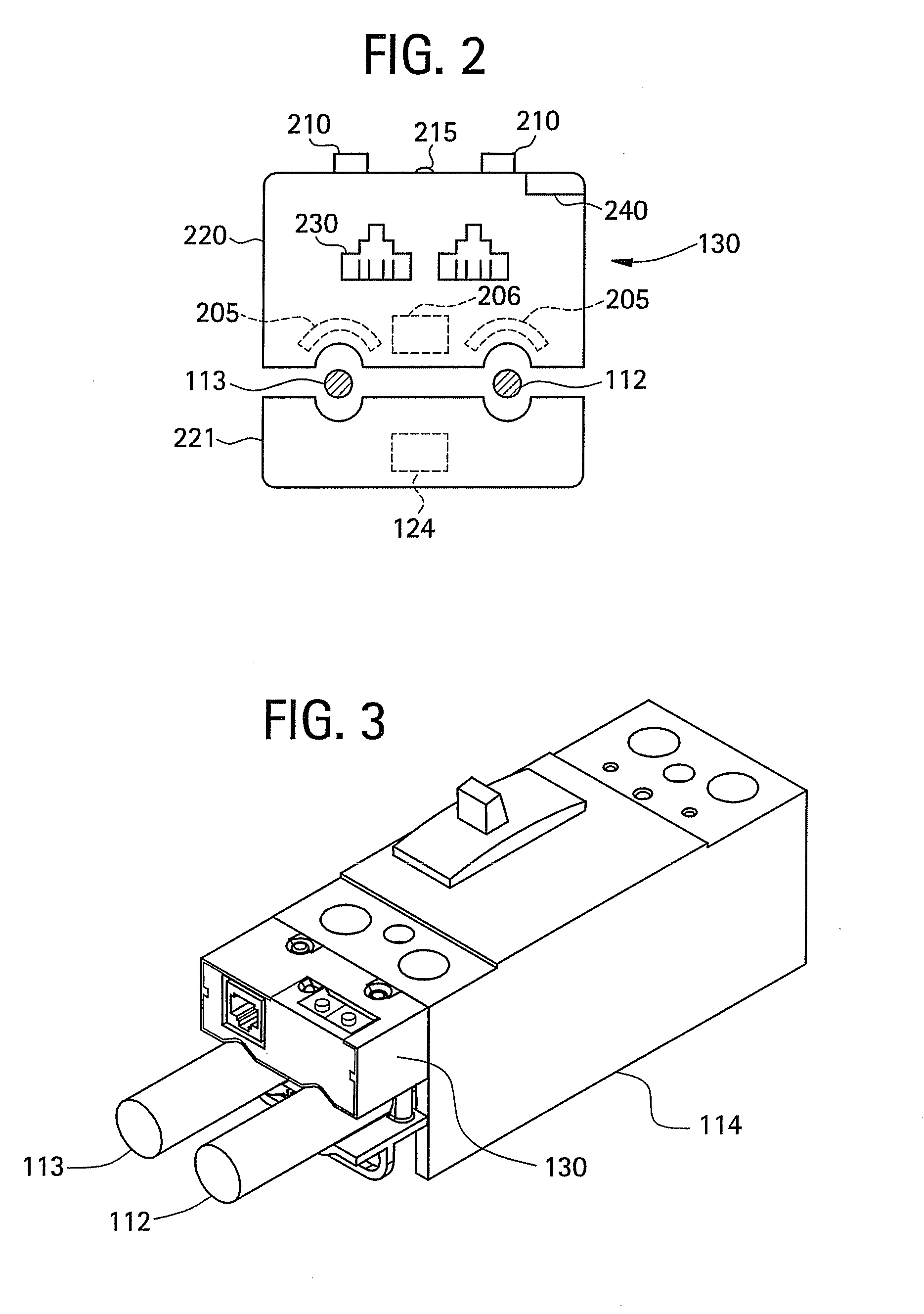
[0017]An embodiment of the invention will provide a compact sub-metering panel that will accurately track and store the power consumption of each suite, or apartment, in a multi-tenant building. Measurements of voltage and current of each suite will be used to calculate the power consumed by the suite. In an embodiment, the compact sub-metering panel will measure the current using a MEMS-based current sensor proximate to a conductor of each sub-metered breaker, and transmit the measurement to a panel-centralized hub. In an embodiment, one of the hub, and a module including the current sensor will measure the voltage, calculate the energy and power consumed by each breaker, and output the energy and power consumption calculations to a central data collector. In an embodiment, the data collector will calculate a bill, based on the energy and power consumed by the particular suite. In an embodiment, the transmission from the hub to data collector can be one of a wired connection and a ...


PUM


Abstract

A current sensing module for disposal proximate a conductor is disclosed. The current sensing module includes a housing having a first section and a second section that together define an opening for receiving the conductor therethrough. The second section is in operable connection with the first section. The current sensing module further includes a micro-electromechanical system (MEMS) based current sensor disposed within the first section proximate the opening for receiving the conductor.

Description

CROSS REFERENCE TO RELATED APPLICATIONS[0001]This application is a continuation-in-part application of U.S. patent application Ser. No. 11 / 536,377, filed Sep. 28, 2006, the contents of which are incorporated by reference herein in their entirety.BACKGROUND OF THE INVENTION[0002]The present disclosure relates generally to electrical power distribution, and particularly to measurement of power for at least one of a plurality of circuits. A building owner of a multi-tenant building, where deregulation has taken effect, can often purchase power from a utility provider in bulk at a wholesale rate, and re-sell it to the tenants. A sub-metering panel allows the building owner to accurately measure & bill the tenants for the power consumed by each tenant.[0003]Sub-metering is traditionally performed by installing a current transformer (CT) on the conductor that is carrying the electrical load. There is one CT per phase of any load that is to be monitored, and each CT has two wire leads that...

Claims


Application Information

Patent Timeline
IPC IPC(8): G01R31/08
CPCG01R1/04G01R15/146G01R15/142G01R15/14G01R15/20
Inventor ROBARGE, DEAN ARTHURCAGGIANO, ROBERT JOSEPHRIVERS, CECILDELICA, ROOSSELY
Owner GENERAL ELECTRIC CO
Why Eureka
Try Eureka