Battery monitoring device and battery monitoring method

a battery monitoring and monitoring device technology, applied in circuit monitoring/indication, instruments, electrochemical generators, etc., can solve the problems of change in charging voltage, charge end current, path resistance of a detection portion, and inability to take into account the path resistance, so as to improve the accuracy of computation of fully charged time.

Inactive Publication Date: 2012-05-24
MITSUMI ELECTRIC CO LTD
View PDF2 Cites 53 Cited by
  • Summary
  • Abstract
  • Description
  • Claims
  • Application Information

AI Technical Summary

Benefits of technology

[0009]In one aspect, the present disclosure provides a battery monitoring device which is capable of computing a permissible charging capacity according to the state of the secondary battery and improving the accuracy of computation of the fully charged time of the secondary battery.

Problems solved by technology

However, in the charging time computation method disclosed in Japanese Laid-Open Patent Publication No. 07-274408, changes in the charging voltage, the charge end current, and the path resistance of a detection portion due to the environmental condition during the charging are not taken into consideration.
Hence, there has been a problem that, if there is a change in the environmental condition (such as temperature), the accuracy of computation of the charging time becomes worse.
Hence, there has been a problem that an error between the computed charging time and the measured charging time is too large.

Method used


Image

  • Battery monitoring device and battery monitoring method
  • Battery monitoring device and battery monitoring method
  • Battery monitoring device and battery monitoring method

Examples


example)

(Example)

SOCfull=−0.026×(139 mΩ+100 mΩ)+105.5+0.05×(4250 mV−4200 mV)

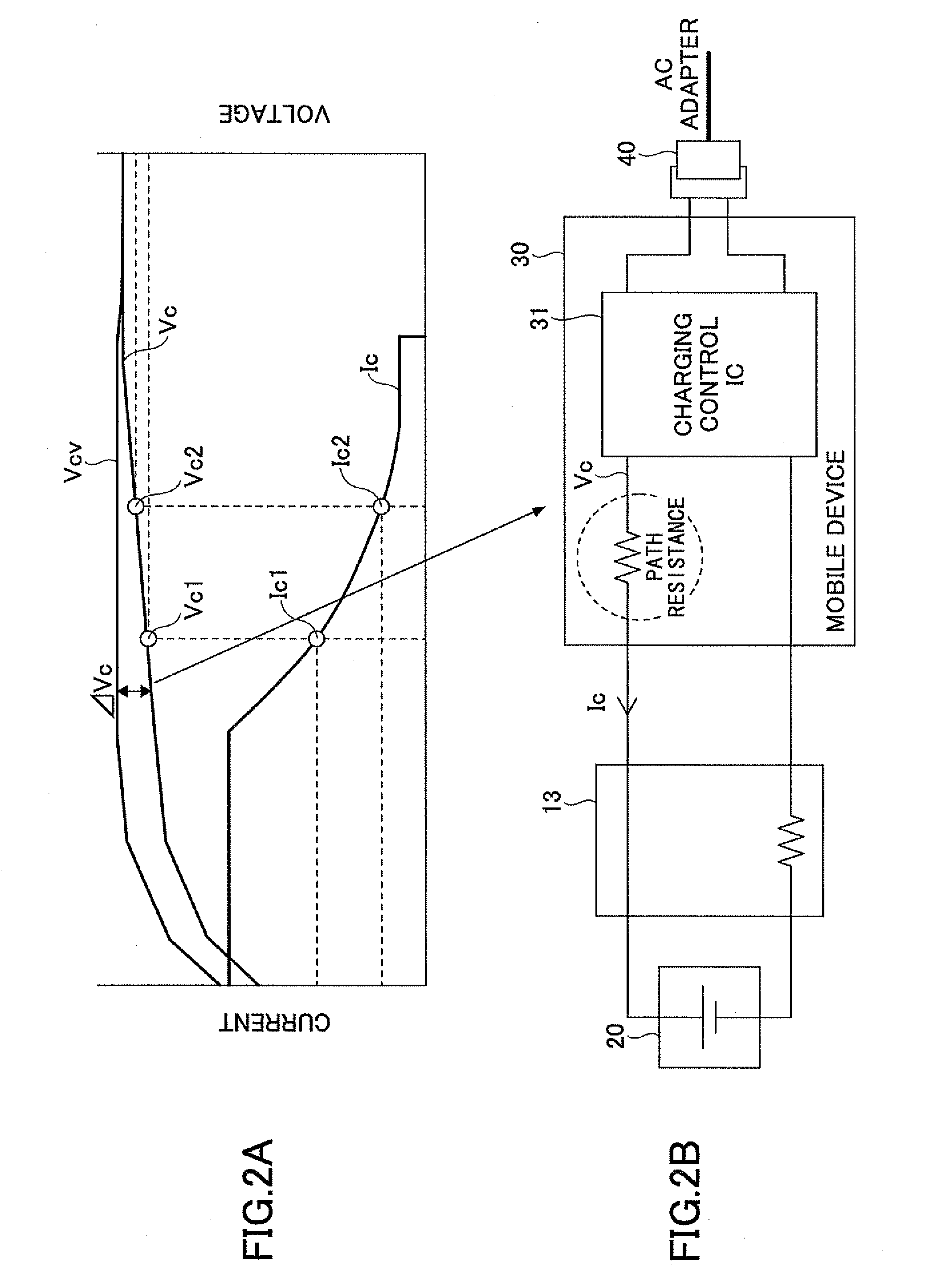
In the above formula, ΔVcv is the voltage which is obtained by subtracting the standard charging voltage of the secondary battery 20 from the computed constant-voltage charging voltage Vcv (ΔVcv=Vcv−standard charging voltage (e.g. 4.2V)).

[0101]The coefficients (αSOC, βSOC, αV) which indicate the characteristics of SOCfull shown in FIG. 7 are stored in the recording unit 52 as the characteristic data.

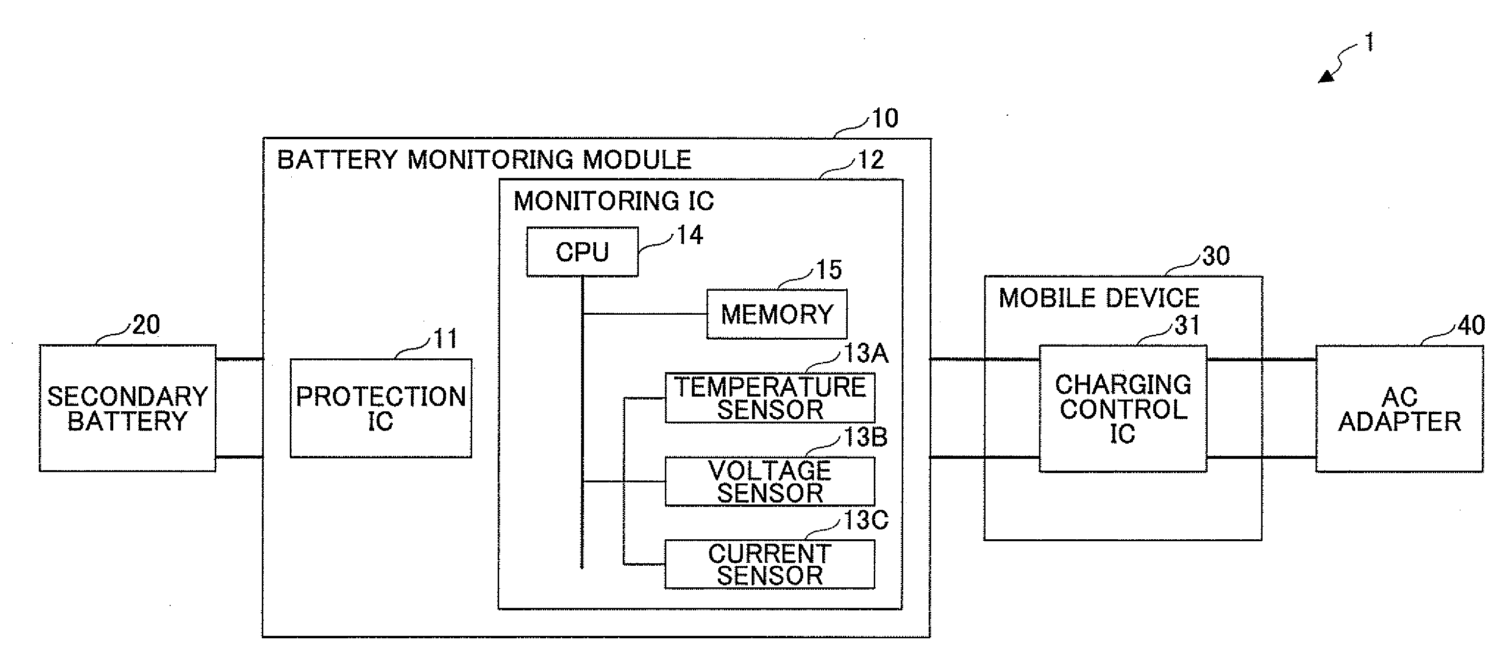
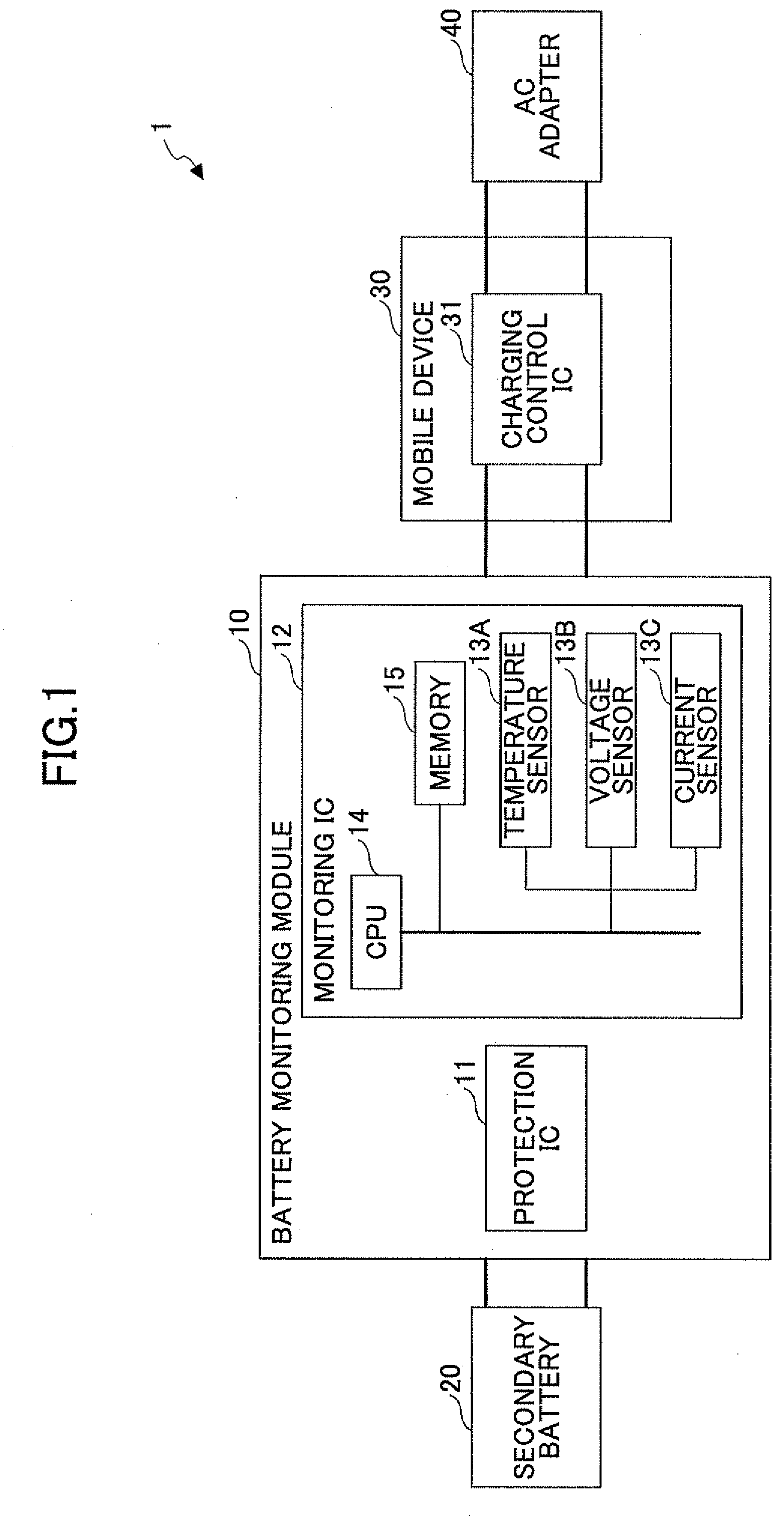
[0102]When the charging current value Ic>0 is detected by the detecting unit 51, the charging time computing unit 55 determines that the processing state is in the charging state, and computes the first charging ratio SOCfull in accordance with the above formula (1) by using the voltage increment ΔVcv, the internal resistance value Rrtn at the present temperature, and the path resistance Rc (computed beforehand).

[0103]The internal resistance value Rrtn at the present temperature may be computed based the ambient temperat...


PUM


Abstract

A battery monitoring device includes a detecting unit which detects a voltage value, a current value and a temperature of a secondary battery, a charging time computing unit which computes a charging time of the battery by using the voltage value, the current value and the temperature detected by the detecting unit, and a determining unit which determines a charging state of the battery. The charging time computing unit is configured to compute a fully charged time of the battery based on a first charging ratio, a constant-current charging ratio, and a second charging ratio.

Description

CROSS-REFERENCE TO RELATED APPLICATION[0001]This application is based upon and claims the benefit of priority of Japanese patent application No. 2010-260657, filed on Nov. 22, 2010, the entire contents of which are incorporated by reference herein.BACKGROUND OF THE INVENTION[0002]1. Field of the Invention[0003]The present disclosure relates to a battery monitoring device and a battery monitoring method.[0004]2. Description of the Related Art[0005]Conventionally, a constant-current, constant-voltage (CC / CV) charging method is known as a method of charging a secondary battery, such as a lithium ion battery, which is used in an electronic device, such as a cellular phone. In the constant-current, constant-voltage charging method, constant-current (CC) charging is first performed, and if a voltage of the secondary battery reaches a predetermined voltage, the CC charging is switched to constant-voltage (CV) charging and the CV charging is subsequently performed, and if a charging current...

Claims


Application Information

Patent Timeline
Patent Type & Authority Applications(United States)
IPC IPC(8): G01R31/36
CPCH02J7/041G01R31/3624G01R31/3842H02J7/0071Y02E60/10H02J7/04H01M10/486H02J7/0049G01R31/389
Inventor HAGIMORI, HITOSHITAKAHASHI, MITSUHIRO
Owner MITSUMI ELECTRIC CO LTD
Why Eureka
Try Eureka