Touch panel and display device comprising the same

a display device and touch panel technology, applied in the field of touch panel and display device, can solve the problems of increasing detection time accordingly, unpleasant operation, and inability to meet the desired detection time, and achieve the effect of shortening the time required for determination, and increasing the accuracy of a calculated touch coordinate valu

Inactive Publication Date: 2010-10-07
MITSUBISHI ELECTRIC CORP
View PDF5 Cites 53 Cited by
  • Summary
  • Abstract
  • Description
  • Claims
  • Application Information

AI Technical Summary

Benefits of technology

[0010]The present invention is intended to solve the above problem, and it is an object of the present invention to provide a touch panel capable of calculating the touch coordinates by interpolating the touch coordinates with high accuracy in a desired detection time even if a large number of detection wires are provided and a display device having a touch panel function capable of increasing the accuracy of a calculated touch coordinate value while shortening the time required for determination of the touch coordinates.
[0012]In the present invention, when the touch of the indicator is detected, detection is performed again with increased detection accuracy and interpolation is performed. Therefore, as compared with the case where the detection accuracy is high all the time, it is possible to shorten the time required for detection while ensuring the detection accuracy. This increases the accuracy of the calculated touch coordinates while shortening the time required for determination of the touch coordinates.

Problems solved by technology

If the capacitance detection sensitivity is set uniformly for all the detection wires, however, when the number of detection wires increases, the detection time accordingly increases and the detection time cannot satisfy a desired detection time (generally, 100 ms or shorter).
This causes an unpleasantness in operation.
If the desired detection time is intended to be satisfied, the capacitance detection sensitivity for one detection wire required for interpolation cannot be ensured and this arises a problem that the touch coordinates cannot be accurately calculated.

Method used


Image

  • Touch panel and display device comprising the same
  • Touch panel and display device comprising the same
  • Touch panel and display device comprising the same

Examples


Embodiment Construction

The First Preferred Embodiment

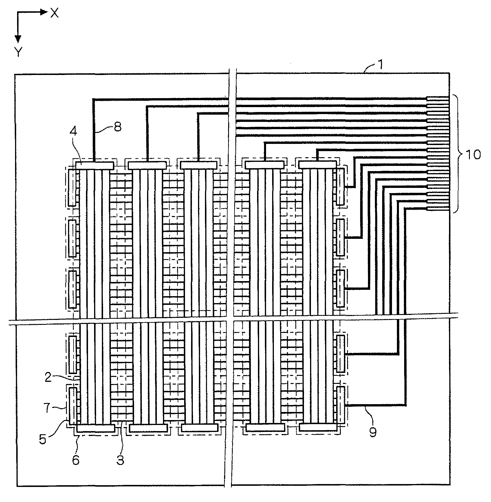
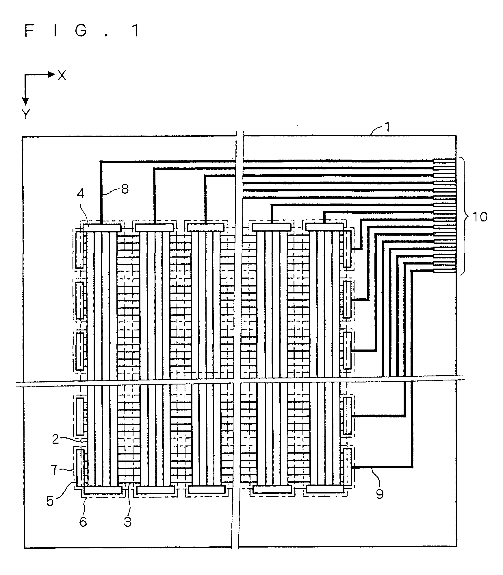
[0028]FIG. 1 is a plan view showing a configuration of a touch screen 1 included in a touch panel in accordance with the first preferred embodiment, and FIG. 2 is a partially sectional perspective view thereof. Hereinafter, the constitution of the touch screen 1 will be discussed with reference to figures. In the following figures including the figure of the second preferred embodiment, reference signs identical to those of FIGS. 1 and 2 represent the same or corresponding constituent elements.

[0029]As shown in FIG. 1, the touch screen 1 comprises a plurality of detection column wires 2 each extending in a column direction (y direction in FIG. 1), which are arranged in parallel in a row direction (x direction in FIG. 1) at a predetermined pitch, and a plurality of detection row wires 3 each extending in a row direction x, which are arranged in parallel in a column direction y at a predetermined pitch. A predetermined number of detection column wires 2 a...


PUM


Abstract

A touch panel capable of calculating touch position coordinates of an indicator with high accuracy in a desired detection time even if a large number of detection wire groups are provided. An oscillator circuit selects one of detection wires selected by a circuit or the like according to a command from a detection control circuit and oscillates. A circuit counts an output signal from the oscillator circuit up to a first count value. A circuit measures a period of the count. A circuit determines that there is a touch when it detects the detection wire of which the measured period is equal to or higher than a threshold value and sends the detection wire giving a maximum value equal to or higher than the threshold value to a circuit as a touch detection wire. The circuit causes the circuit or the like to select the touch detection wire and the detection wires adjacent thereto on both sides, the circuit counts up until the count value becomes a second count value larger than the first count value, and the circuit measures the count period. The circuit performs interpolation on the basis of the count value obtained by subtracting a background capacitance value from a measured value obtained by the circuit, to thereby determine the touch coordinates.

Description

TECHNICAL FIELD[0001]The present invention relates to a touch panel and a display device comprising the touch panel.BACKGROUND ART[0002]As one of excellent user interface means, a touch panel which detects a touch of a finger or the like and specifies the position coordinates thereof has received attention.[0003]and various types of touch panels such as a resistance film type and a capacitive touchscreen system are commercialized.[0004]The capacitive touchscreen system includes a projected capacitive touchscreen system capable of detecting a touch even if the front surface side of the touch screen in which a touch sensor is incorporated is covered with a protection plate such as a glass plate having a thickness of about several mm. This system has the advantages that excellent fastness can be achieved since the protection plate can be arranged on the front surface, that detection of a touch is possible even when a user wears gloves, that long-life is ensured since this system has no...

Claims


Application Information

Patent Timeline
Patent Type & Authority Applications(United States)
IPC IPC(8): G06F3/045
CPCG06F3/044G06F3/0416G06F3/04166G06F3/04164G06F3/0445G06F3/0446
Inventor AGARI, MASAFUMINAKAGAWA, NAOKIMORI, SEIICHIROMURAI, HIROYUKI
Owner MITSUBISHI ELECTRIC CORP
Why Eureka
Try Eureka