Method to improve fuel economy in lean burn engines with variable-displacement-like characteristics

a variable displacement, engine technology, applied in the direction of machines/engines, electric control, ignition automatic control, etc., can solve the problem of higher combustion stability limit than, and achieve the effect of increasing heat, increasing engine load condition, and increasing ignition timing retard

Inactive Publication Date: 2004-07-06
FORD GLOBAL TECH LLC
View PDF138 Cites 69 Cited by
  • Summary
  • Abstract
  • Description
  • Claims
  • Application Information

AI Technical Summary

Benefits of technology

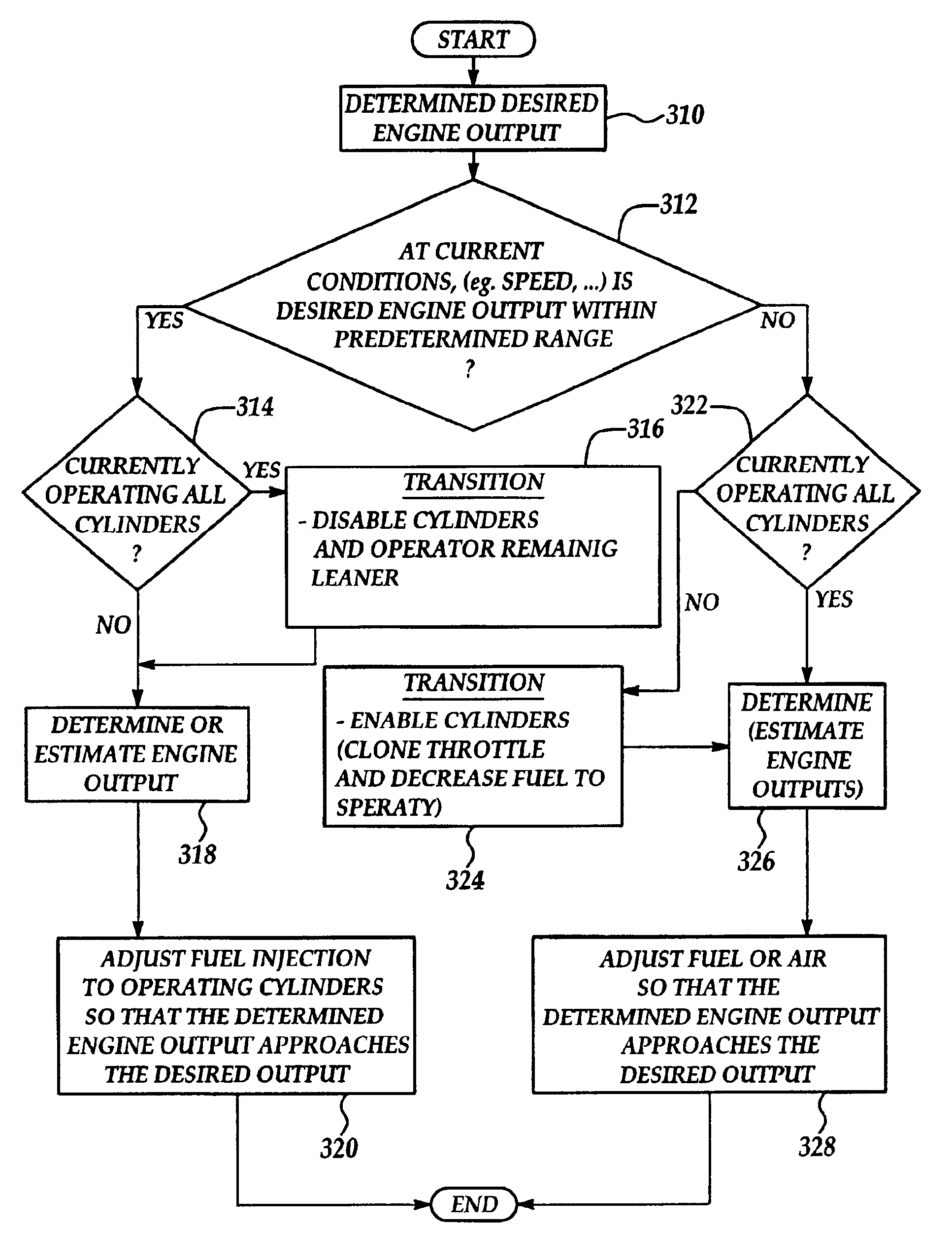
By operating some of the cylinders with only inducted air, and combusting an air / fuel mixture in the other combustion chambers when desired engine output falls below a predetermined amount, the combustion chamber torque of the operating combustion chamber is increased while the overall engine torque falls. In this way, since the combusting chambers are operating at higher loads, they will have a higher combustion stability limit than heretofore possible. This higher limit may then be used to operate the combusting combustion chambers leaner than heretofore possible, resulting in still added fuel economy benefits.
In other words, if a large engine load is placed on the engine and adjustment of engine air flow and the first cylinder group ignition timing to the optimal ignition timing is insufficient to maintain the desired engine idle speed, then additional torque is supplied from the second cylinder group by advancing the ignition timing towards the optimal ignition timing. While this reduces the engine heat generated, it only happens for a short period of time to maintain engine idle speed, and therefore, has only a minimal effect on catalyst temperature. Thus, according to the present invention, it is possible to quickly produce a very large increase in engine output since the engine has significant amount of ignition timing retard between the first and second cylinder groups.

Problems solved by technology

In this way, since the combusting chambers are operating at higher loads, they will have a higher combustion stability limit than heretofore possible.

Method used


Image

  • Method to improve fuel economy in lean burn engines with variable-displacement-like characteristics
  • Method to improve fuel economy in lean burn engines with variable-displacement-like characteristics
  • Method to improve fuel economy in lean burn engines with variable-displacement-like characteristics

Examples


example 2

of FIG. 13I illustrates operation according to the present invention. In particular, the ignition timing of the second group (spk2') is substantially more retarded than the ignition timing of the first cylinder group of Example 2 (spk2). Further, the air and fuel amounts (a2, f2) are greater than the air amounts in Example 1. As a result of operation , the first cylinder group produces engine torque (T2), while the second cylinder group produces engine torque (T2'). In other words, the first cylinder group produces more engine torque than when operating according to Example 1 since there is more air and fuel to combust. Also note that the first cylinder group of Example 2 has more ignition retard from optimal timing than the ignition timing of group 1 of Example 1. Also, note that the engine torque from the second cylinder group (T2') is less than the engine torque produced by the first and second cylinder group of Example 1, due to the severe ignition timing retard from optimal tim...


PUM


Abstract

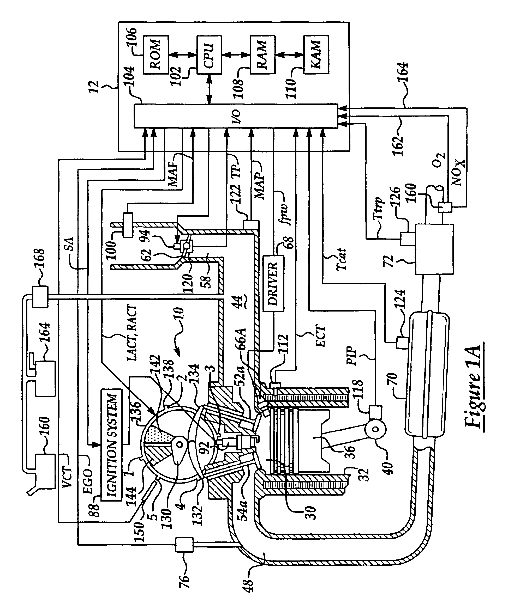
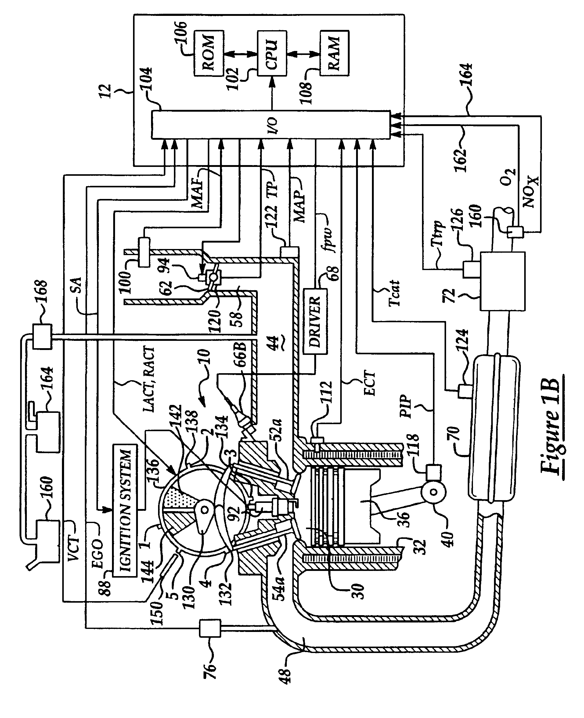
A method is disclosed for controlling operation of an engine coupled to an exhaust treatment catalyst. Under predetermined conditions, the method operates an engine with a first group of cylinders combusting a lean air / fuel mixture and a second group of cylinders pumping air only (i.e., without fuel injection). In addition, the engine control method also provides the following features in combination with the above-described split air / lean mode: idle speed control, sensor diagnostics, air / fuel ratio control, adaptive learning, fuel vapor purging, catalyst temperature estimation, default operation, and exhaust gas and emission control device temperature control. In addition, the engine control method also changes to combusting in all cylinders under preselected operating conditions such as fuel vapor purging, manifold vacuum control, and purging of stored oxidants in an emission control device.

Description

BACKGROUND OF INVENTION1. Field of the InventionThe field of the invention relates generally to variable displacement engines for providing improved fuel economy.2. Background of the InventionVariable displacement engines are known in which the intake valves of selected cylinders are mechanically disabled and the remaining cylinders continue to operate. This results in improved fuel economy because the remaining cylinders operate with a wider throttle angle than is the case when all cylinders are operating.The inventors herein have recognized numerous problems with the prior approach to variable displacement engines. One particular problem is that complex mechanical devices are required to deactivate the intake valves. Another problem is that rough idle conditions may result when in the variable displacement mode, particularly for engines in which the ignition firing order is not limited to each engine bank such as a V-8 engine. It has therefore been common not to operate such engin...

Claims


Application Information

Patent Timeline
Patent Type & Authority Patents(United States)
IPC IPC(8): F01N3/08F02D17/00F02D41/14F02D41/02F02D17/02F02D41/36F02D41/32F01N7/02F01N7/00F02D41/30F01N7/04F01N3/20F02P5/15F01N3/24F01N3/28F01N13/02F01N13/04F01N13/10F02D29/02F02D41/00F02D41/16F02M25/08
CPCF01N3/0814F02D17/02F02D41/0032F02D41/0087F02D41/0225F02D41/0235F02D41/1475F01N13/009F01N13/011F01N3/0842Y10T477/68F01N13/107F01N2560/026F02D13/0215F02D41/0072F02D41/0082F02D41/027F02D41/1456F02D41/3017F02D41/3029F02D41/307F02D2250/18F02D2250/21F02D2250/41F02D17/00F02D35/00
Inventor SURNILLA, GOPICHANDRAMICHELINI, JOHN OTTAVIOROTH, JOHN M.
Owner FORD GLOBAL TECH LLC
Why Eureka
Try Eureka