Recessed LED lighting fixture

a led lighting and recessed technology, applied in the field of lighting fixtures, can solve the problems of generating substantial amounts of heat, affecting the appearance of the room, and affecting the appearance of the room, and achieve the effect of reducing the amount of heat generated

Active Publication Date: 2013-06-27
CORDELIA LIGHTING
View PDF0 Cites 80 Cited by
  • Summary
  • Abstract
  • Description
  • Claims
  • Application Information

AI Technical Summary

Benefits of technology

[0008]The lighting fixture includes an interchangeable trim ring having an open center with a sloped wall defining a reflector that is covered in a light reflective material, wherein the reflector overlies the sloped wall of the cavity. The trim ring further includes a flat annular surface engaging the flat surface of the heat sink flange for thermal conduction therebetween to reduce heat generated by the LED driver and LED array.

Problems solved by technology

Ideally, such fixtures are designed to be visually unobtrusive in that very little of the lighting fixture is visible from below the ceiling.
Some light sources generate substantial amounts of heat, so much so that the rating of the light fixture must be displayed and warnings given that light sources above a certain wattage could pose an overheating problem and are not to be used.
Such wattage limits imposed by the lighting fixtures can undesirably limit the amount of light furnished by the fixture.
For example, lighting fixtures located in higher ceilings, which are more common today, or lighting fixtures that are meant to shine at an angle other than perpendicular to illuminate an object, may not provide enough light for the object if lower wattage light sources must be used.

Method used


Image

  • Recessed LED lighting fixture
  • Recessed LED lighting fixture
  • Recessed LED lighting fixture

Examples


Embodiment Construction

[0023]The present invention in various preferred embodiments is directed to a recessed lighting fixture that uses a LED as the light source to conserve energy and for long life of the light source as compared to, for example, incandescent bulbs. The present invention light fixture can be installed in a residential new construction or used to retrofit a pre-existing home or building that has recessed lighting fixtures.

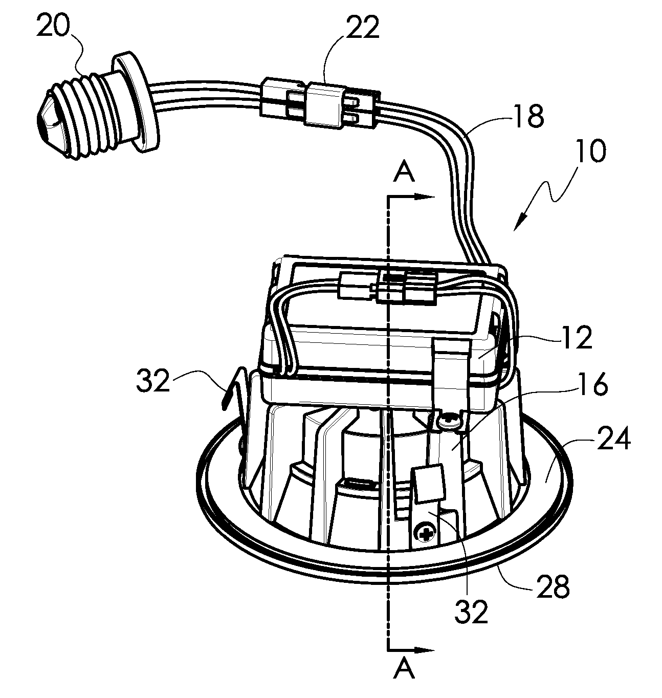
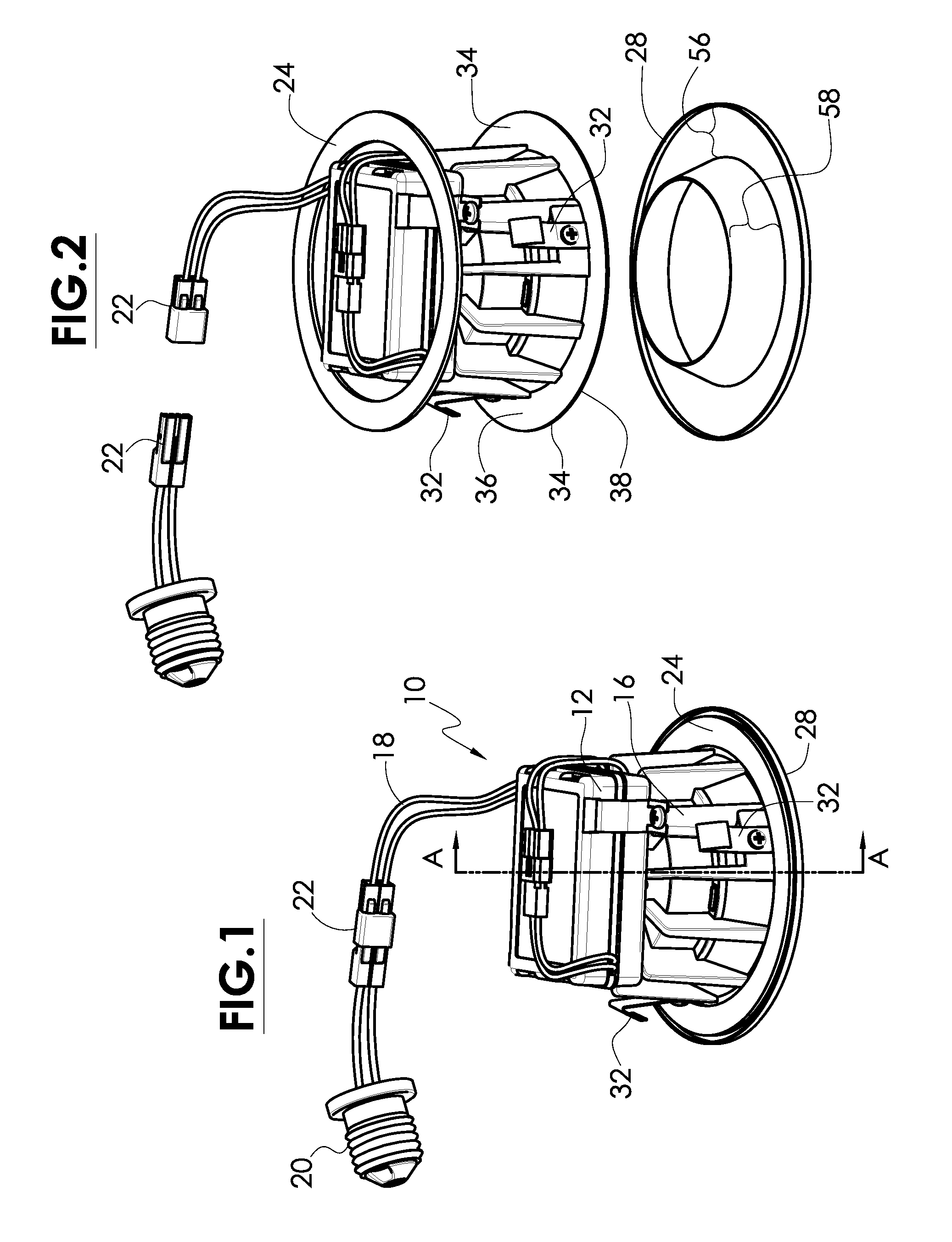
[0024]FIG. 1 is a perspective view of a preferred embodiment recessed lighting fixture 10. The lighting fixture is has a LED light source that is powered by an LED driver 12, which is the power supply and voltage control for the LED light source. In normal operation, the LED light source and the LED driver 12 generate a lot of heat, so a heat sink 16 is used to conduct and dissipate heat from both. An electrical connection or power cables 18 supplies electrical power to the LED driver 12. The power cables 18 terminate in an Edison type screw plug 20. This Edison screw p...


PUM

PropertyMeasurementUnit
aspect ratioaaaaaaaaaa
conductiveaaaaaaaaaa
thermalaaaaaaaaaa

Abstract

A recessed lighting fixture providing illumination from a light source including a plurality of light emitting diodes (LEDs) wherein the fixture is placed within the ceiling space above a ceiling panel or wall. The fixture has a low aspect ratio heat sink. An interchangeable trim ring has an integrated light reflector and attaches to the bottom of the heat sink via rare earth or super magnets. A flange of the heat sink and a flat annular surface of the trim ring engage each other, providing a large contact surface to enable conductive heat transfer. The flange and flat annular surface are located below the ceiling panel, which is at room temperature to help cool the recessed LED lighting fixture through radiation and air convection.

Description

BACKGROUND[0001]The present invention relates generally to lighting fixtures and, more particularly, to a LED recessed lighting fixture that provides improved heat dissipation.[0002]Recessed lighting fixtures are well known in the art. Ideally, such fixtures are designed to be visually unobtrusive in that very little of the lighting fixture is visible from below the ceiling. However, some trim portions are visible as well as the light sources. An opening is cut into the ceiling into which most of the lighting fixture is mounted so that very little extends below the plane of the ceiling. A trim piece or trim ring, which may take the form of a bezel, is generally located at the opening to enhance the appearance of the light fixture and conceal the hole cut into the ceiling. Typically, the trim piece is slightly below the planar surface of the ceiling.[0003]Such bezels or other types of trim pieces also include insulation located between the trim piece and the ceiling. In many cases, r...

Claims


Application Information

Patent Timeline
Patent Type & Authority Applications(United States)
IPC IPC(8): F21V29/00F21V5/04
CPCF21V29/004F21V29/89F21S8/026F21V7/041F21V7/22F21V17/002F21V17/105F21V21/044F21V23/007F21Y2101/02F21Y2105/001F21V21/041F21V29/713F21V29/773F21V31/005F21V23/001F21V23/06F21Y2105/10F21Y2115/10F21V7/24F21V7/28
Inventor CHANG, SETHNGUYEN, HUAN CAOMADDEN, JAMES
Owner CORDELIA LIGHTING
Why Eureka
Try Eureka