Multipoint sensing method for capacitive touch panel

a capacitive touch panel and multi-point sensing technology, applied in the field of touch panel technology, can solve the problems of reducing the s/n ratio (signal-to-noise ratio) of the detection signals measured by the capacitive sensing circuit, prolonging the response time, noise interference with the detection signals, etc., to achieve rapid detection of the whole touch panel, save circuit fabrication manufacturing cost, and save sensing time.

Inactive Publication Date: 2010-05-13
NAT CHIAO TUNG UNIV
View PDF10 Cites 43 Cited by
  • Summary
  • Abstract
  • Description
  • Claims
  • Application Information

AI Technical Summary

Benefits of technology

[0008]The present invention has been accomplished under the circumstances in view. It is therefore a main objective of the present invention to provide a multipoint sensing method for capacitive touch panel, which is a low-noise and rapid-response sensing method satisfying the detecting requirements of big size touch panels. Another objective of the present invention is to provide the multipoint sensing method applied with only a few number of sensing circuits to achieve rapid detection of the whole touch panel, saving the manufacturing cost of circuit fabrication.
[0009]To achieve these objectives of the present invention, the multipoint sensing method uses a capacitive sensing circuit to detect the voltage variation of a plurality of first electrodes and second electrodes, which are electrically insulated with each other, and where the voltage variation is happened, the capacitive sensing circuit measures the vertical capacitance at the intersected point that is crossed by and between the detected first electrode and second electrode and then compares the vertical capacitance thus measured with the initial vertical capacitance thus measured before touch event at the same intersected point to determine the points to be touched when the comparison result shows a difference. This method eliminates the procedure of the prior art technique to consequently detect the vertical capacitance at every intersected point between the first electrodes and the second electrodes, thus saving much sensing time. Further, according to the multipoint sensing method of the present invention, one single capacitive sensing circuit can achieve rapid detection of the whole touch panel, and therefore the invention saves much of the circuit manufacturing cost.

Problems solved by technology

If the touch panel has a big size or needs to proceed the detection of multiple touch points, the parasitic resistance presenting in the current path may affect the detection signals for determination of the touch point, extend the charging time of the electrode capacitance and thereby causing an extension of the response time of the capacitive sensing circuit, and give rise to noise interference with the detection signals along the charge transfer path as well as decrease the S / N ratio (signal-to-noise ratio) of the detection signals measured by the capacitive sensing circuit.
Taking an example as regular transparent electrodes applied for conducting wires of touch panel and made from ITO (indium-tin oxide) material, which having a higher resistive component than other regular metal wires and with a relatively increasing rate of the resistance subject to increase the touch panel size, the resistive factor of the ITO material results in low response speed of the capacitive sensing circuit, and additional sensing circuits will be required if it is necessary for accelerating the response speed.
However, increasing the number of sensing circuits greatly increases the circuit installation space and manufacturing cost.
In case of using a different electrode material to decrease the resistance in the charge transfer path, electrode materials currently available on the market do not have as high transmittance for visible light as ITO electrodes to maintain light transparency required for the touch panel.
Therefore, the circuit structure of this ASIC is complicate and expensive to manufacture, increasing the manufacturing cost of the touch panel.
This technique simplifies the circuit structure and saves much time in waiting for charge re-distribution of the capacitance.
However, when this technique is used for multiple touch points application, more number of switch devices and sensing capacitors must be provided, increasing circuit installation space and manufacturing cost as well.

Method used


Image

  • Multipoint sensing method for capacitive touch panel
  • Multipoint sensing method for capacitive touch panel
  • Multipoint sensing method for capacitive touch panel

Examples


Embodiment Construction

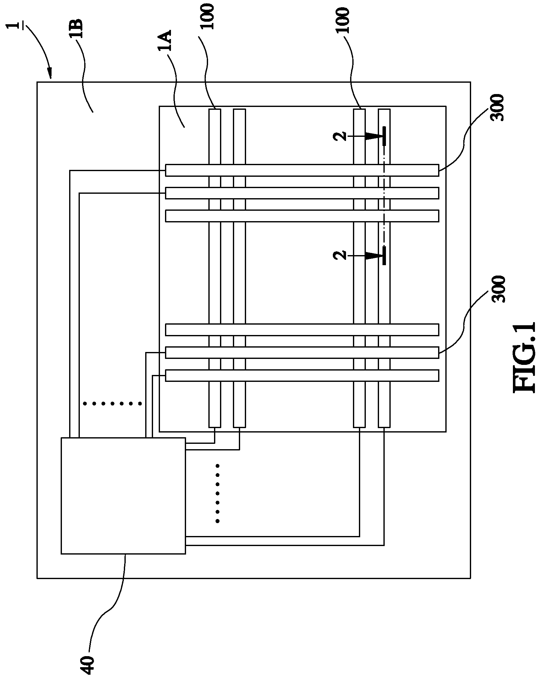
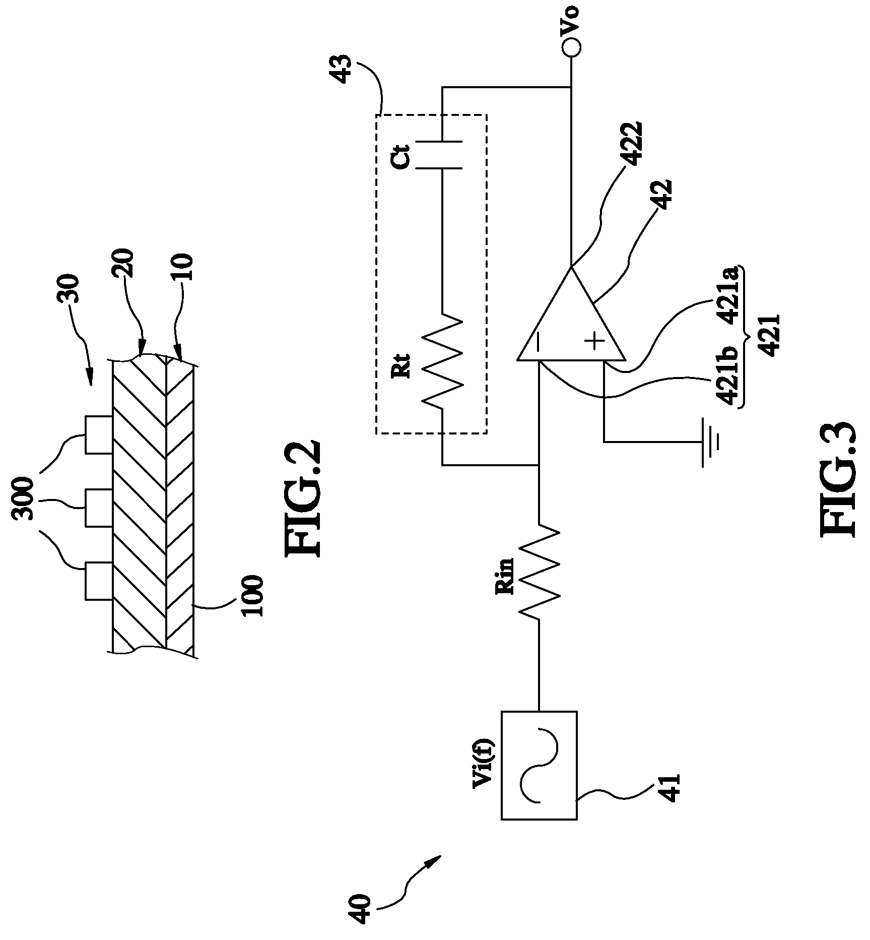
[0016]Referring to FIGS. 1 and 2, a touch panel 1 is shown comprising a display region 1A and a peripheral circuit region 1B. The display region 1A is a touch-sensing region, comprising a bottom electrode layer 10, a top electrode layer 30, and an insulation layer 20 sandwiched between the bottom electrode layer 10 and the top electrode layer 30. The peripheral circuit region 1B comprises a capacitive sensing circuit 40 for detecting and recognizing the sensed touch points of the display region 1A. The bottom electrode layer 10 has row electrodes 100 arranged in parallel at a predetermined interval and extending to the peripheral circuit region 1B for electrical connection to the capacitive sensing circuit 40. The insulation layer 20 is made of an electrically insulated material, and adapted to isolate the bottom electrode layer 10 and the top electrode layer 30. The top electrode layer 30 has column electrodes 300 arranged in parallel at a predetermined interval and orthogonal to t...


PUM


Abstract

A multi-point sensing method used in a capacitive touch panel is disclosed to detect the voltage variation of every electrode patterned on two parallel electrode layers by means of a capacitive sensing circuit, and measure the vertical capacitance at the intersection crossed by the electrodes of the two electrode layers where the voltage variation is detected, and then compare the vertical capacitance thus measured with the initial vertical capacitance at the same intersection before touch, as a result, the intersection corresponding to the measured vertical capacitance can be determined as the touch point when the comparison result shows different.

Description

BACKGROUND OF THE INVENTION[0001]1. Field of the Invention[0002]The present invention relates to touch panel technology and more particularly, to a multipoint sensing method for capacitive touch panel.[0003]2. Description of the Related Art[0004]A touch panel technology of capacitive type is capable of recognizing the touch of a human body by means of detecting the variation of capacitance. The touch panel is normally comprised of electrode arrays and a capacitive sensing circuit. When sensing signals are inputted onto a top electrode layer and a bottom electrode layer of the electrode arrays, the capacitive sensing circuit detects the specific capacitance of a plurality of capacitors which are formed between the two electrode layers and located at each intersection crossed by row electrodes and column electrodes patterned respectively on the two electrode layers. Therefore, the capacitive sensing circuit can judge whether any human touch happened on the touch panel to cause an equi...

Claims


Application Information

Patent Timeline
Patent Type & Authority Applications(United States)
IPC IPC(8): G06F3/045
CPCG06F3/044G02F1/13338G06F2203/04104G06F3/0445G06F3/0446
Inventor CHEN, JIAN TINGCHAO, PAUL C.P.RUAN, JYUN-YAO
Owner NAT CHIAO TUNG UNIV
Why Eureka
Try Eureka