

Compressor/expander of the rotating vane type
a compressor/expander, rotating technology, applied in the direction of steam/vapor condensers, rotary piston engines, lighting and heating apparatuses, etc., can solve the problems of excessive energy loss, achieve low rolling friction, reduce internal energy loss, and avoid unnecessary rubbing
- Summary
- Abstract
- Description
- Claims
- Application Information
AI Technical Summary
Benefits of technology
Problems solved by technology
Method used
Image

Examples
Embodiment Construction
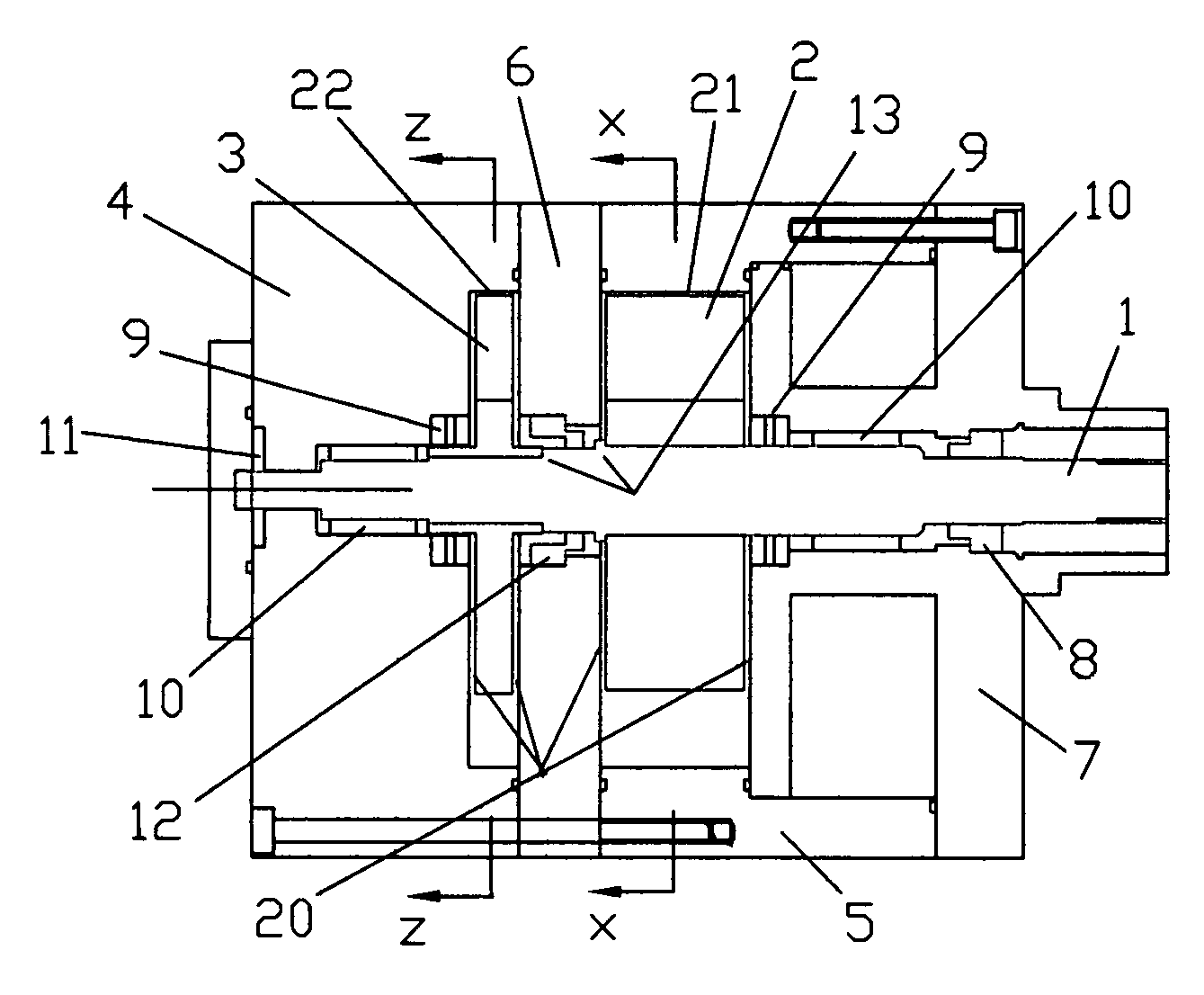
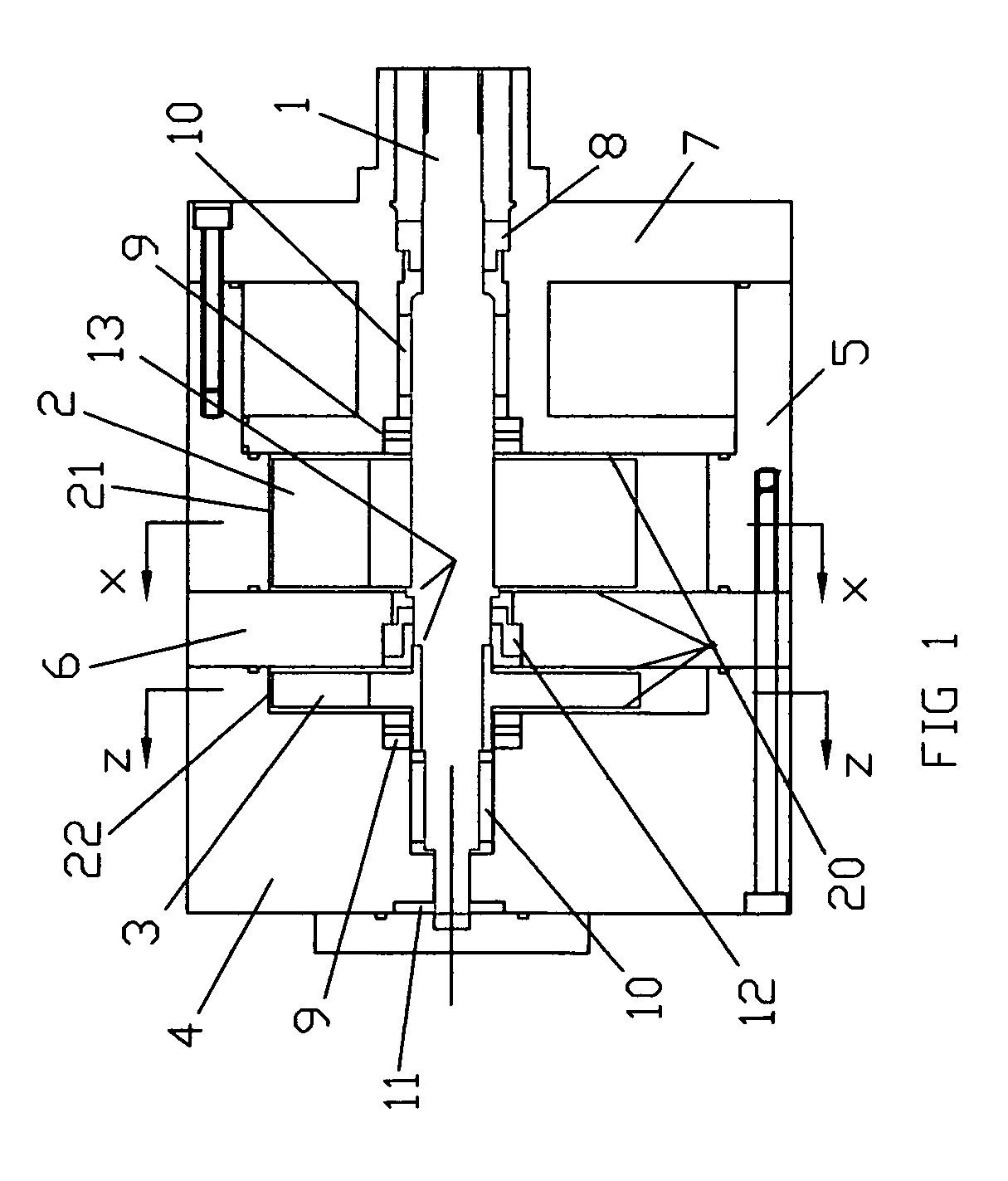
[0019]FIG. 1 shows an axial section through the vane-type compressor / expander, and should be read in conjunction with FIGS. 2, 3 and 5. A common shaft 1 turns a compressor rotor 2, and expander rotor 3. The compressor compresses refrigerant as in a conventional air-conditioning system, while a control device is followed by the expander to recover expansion energy, as explained in detail in U.S. Pat. No. 5,819,554, and shown in FIG. 5.
[0020]Additional features of FIG. 1 are an expander casing 4, compressor casing 5, and separating plate 6. Also shown are an oil / refrigerant separator chamber 7, a shaft seal 8, thrust bearing 9, shaft bearing 10, oil pump 11, a seal 12 riding on shaft 1 and separating compressor 2 and expander 3 rotors, and shaft shoulders 13 which keep the rotors 2 and 3 from rubbing the separating plate 6. Also shown are the fine clearances 20 between rotating components 2,3 and stationary components 4,6,7.
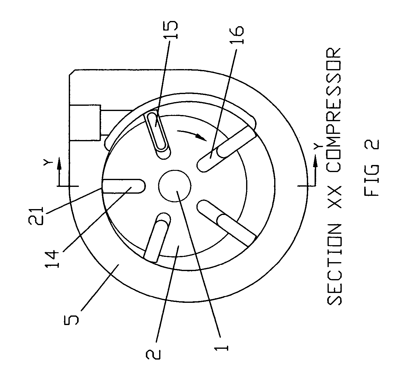
[0021]FIG. 2 is a radial section (xx of FIG. 1) through the c...
PUM
 Abstract
Description
Claims
Application Information