Oscillation amount adjusting device for oscillating roller

a technology of oscillating roller and adjusting device, which is applied in the direction of printing press parts, printing presses, printing, etc., can solve the problems of uneven thickness of ink film, affecting printing adversely, and difficult installation of the device in view of the arrangement of the roller and its relation with the other devices

Inactive Publication Date: 2005-01-27
KOMORI CORP
View PDF9 Cites 0 Cited by
  • Summary
  • Abstract
  • Description
  • Claims
  • Application Information

AI Technical Summary

Problems solved by technology

However, this oscillation amount adjusting device has a large-scale drive system composed of a rotating drum, a shaft, a lever, and a link plate, thus requiring a large space, posing the problem that its installation may be difficult in view of roller arrangement and its relation with other devices.
Thus, the plurality of oscillating rollers simultaneously stop at the position of the swing end, presenting the problem that the thickness of an ink film tends to be uneven.
Also, the plurality of oscillating rollers simultaneously stop and begin to move in the reverse direction, causing the problem that shock due to load increases to affect printing adversely.
Thus, a burden is imposed on the operator.
Hence, if, after adjustment, the printing press is driven and the adjustment is found to be unsuccessful, the printing press must be shut down and adjusted again, thus posing the problem of taking time.

Method used


Image

  • Oscillation amount adjusting device for oscillating roller
  • Oscillation amount adjusting device for oscillating roller
  • Oscillation amount adjusting device for oscillating roller

Examples


first embodiment

[0066] First Embodiment

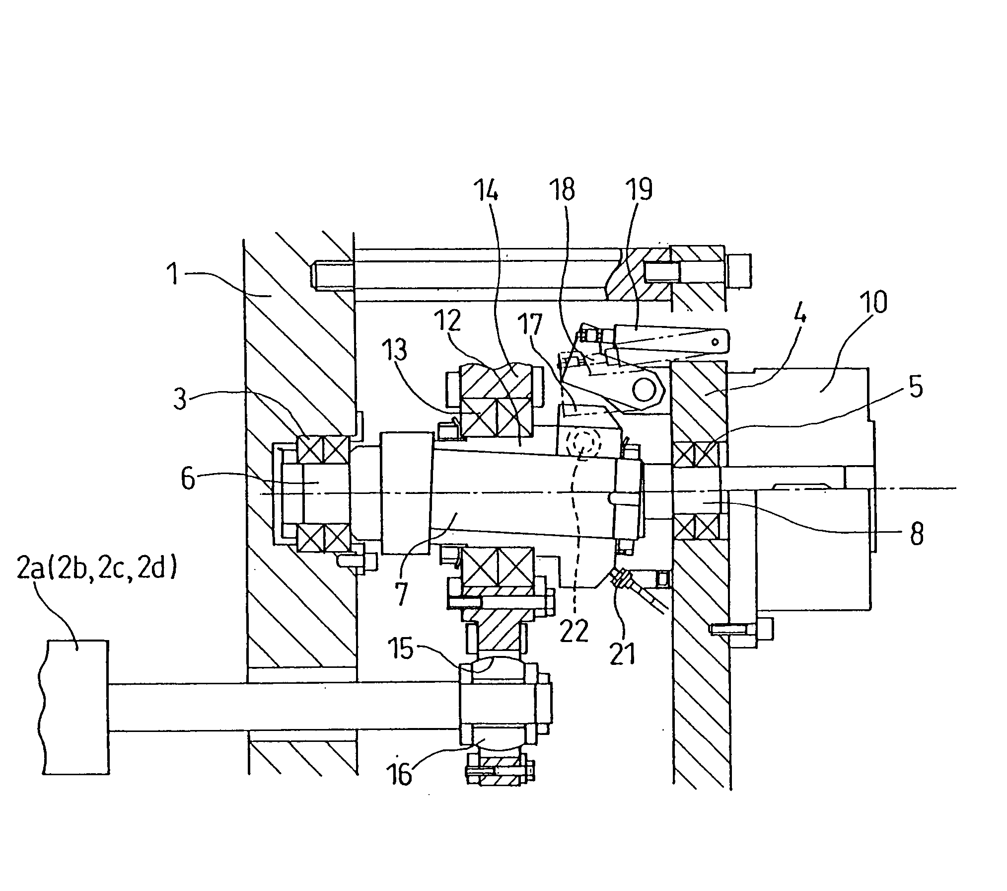
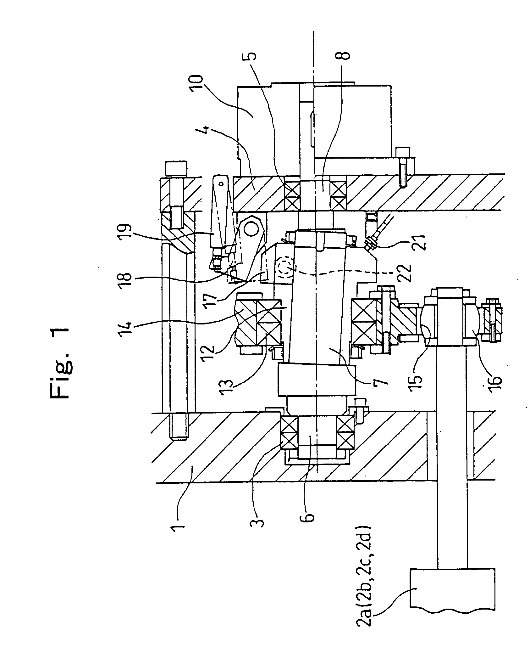
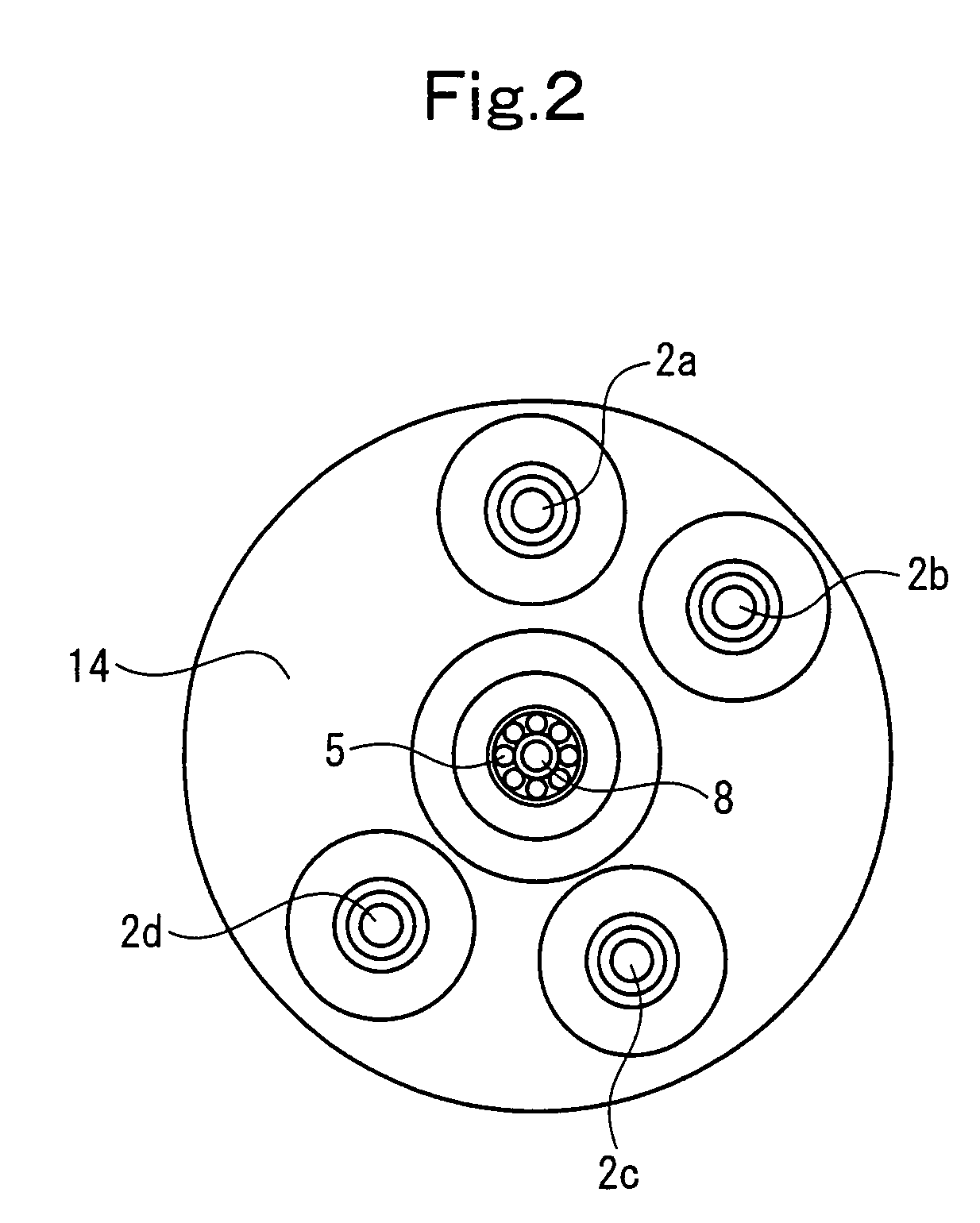
[0067]FIG. 1 is a front sectional view of an oscillating roller swing device of an inking device in a printing press, showing a first embodiment of the present invention. FIG. 2 is a side view of essential parts thereof. FIG. 3 is a control block diagram. FIG. 4 is a flow chart for oscillation amount control. FIG. 5 is a flow chart for the oscillation amount control. FIG. 6 is a flow chart for the oscillation amount control.

[0068] As shown in FIGS. 1 and 2, four oscillating rollers 2a, 2b, 2c, and 2d are journaled by a frame 1 of an inking device. A rotating shaft 6, which is journaled by a bearing 3 provided in the frame 1 and a bearing 5 of a support plate 4 screwed to the frame 1, is provided in a middle portion nearly equally spaced from these oscillating rollers 2a, 2b, 2c, and 2d.

[0069] The rotating shaft 6 is composed of an inclined shaft portion 7 and a parallel shaft portion 8 located adjacently, the inclined shaft portion 7 being inclined with resp...

second embodiment

[0108] Second Embodiment

[0109]FIG. 7 is a front sectional view of an oscillating roller swing device of an inking device in a printing press, showing a second embodiment of the present invention. FIG. 8 is a control block diagram. FIG. 9 is a flow chart for oscillation amount control.

[0110] This embodiment is an embodiment in which the rotating shaft 6, which supports the sleeve 12 in the First Embodiment rotatably at the inclined shaft portion 7, is rotated and driven via a gear 51 by the drive motor 28 for driving the entire printing press, and a home position phase detection sensor 52, such as an optical sensor, for detecting a phase home position reference at the parallel shaft portion 8 of the rotating shaft 6 is annexed to the support plate 4. Other features are the same as those in the First Embodiment.

[0111] The drive motor 28 and the air cylinder 19 are driven and controlled by a control device 30B, as shown in FIG. 8.

[0112] The control device 30B comprises CPU, ROM, and...

third embodiment

[0129] Third Embodiment

[0130]FIG. 10 is a front sectional view of an oscillating roller swing device of an inking device in a printing press, showing a third embodiment of the present invention. FIG. 11 is a control block diagram. FIG. 12 is a flow chart for oscillation amount control. FIG. 13 is a flow chart for the oscillation amount control. FIG. 14 is a flow chart for the oscillation amount control.

[0131] As shown in FIG. 10, four oscillating rollers 2a, 2b, 2c, and 2d are journaled by a frame 1 of an inking device. A rotating shaft 6, which is journaled by a bearing 3 provided in the frame 1 and a bearing 5 of a support plate 4 screwed to the frame 1, is provided in a middle portion nearly equally spaced from these oscillating rollers 2a, 2b, 2c, and 2d.

[0132] The rotating shaft 6 comprises an inclined shaft portion 7 and a parallel shaft portion 8 located adjacently, the inclined shaft portion 7 being inclined with respect to the axes of the oscillating rollers 2a, 2b, 2c, a...


PUM


Abstract

An oscillation amount adjusting device for an oscillating roller has a sleeve detent plate for restraining the rotation of a sleeve. An operator manually loosens a sleeve locking bolt to render the sleeve rotatable relative to a rotating shaft supporting the sleeve. The rotation of the sleeve is restrained by the sleeve detent plate. In this state, the rotating shaft supporting the sleeve is rotated by an oscillation drive motor to adjust the oscillation amount of oscillating rollers.

Description

CROSS REFERENCE TO RELATED APPLICATION [0001] The entire disclosure of Japanese Patent Application No. 2003-200299 filed on Jul. 23, 2003, including specification, claims, drawings, and summary, is incorporated herein by reference in its entirety. BACKGROUND OF THE INVENTION [0002] 1. Field of the Invention [0003] This invention relates to an oscillation amount adjusting device for an oscillating roller in an inking device of a printing press. More specifically, the invention relates to an oscillation amount adjusting device which can make adjustment by remote and automatic control using a motor while achieving space saving without exerting adverse influence on printing. [0004] 2. Description of the Related Art [0005] In an inking device of a printing press, ink in an ink reservoir is sequentially fed to many distribution rollers via ink ductor rollers. In the distribution rollers, the ink is uniformly distributed, and transferred to a printing plate supported on the circumferential...

Claims


Application Information

Patent Timeline
Patent Type & Authority Applications(United States)
IPC IPC(8): B41F31/15
CPCY10S101/38B41F31/15
Inventor KUSAKA, AKEHIROFUSEKI, TAKASHI
Owner KOMORI CORP
Why Eureka
Try Eureka