Swivelable mount for attaching a binding to a snowboard

Inactive Publication Date: 2005-02-10
FIEBING JON
View PDF15 Cites 20 Cited by
  • Summary
  • Abstract
  • Description
  • Claims
  • Application Information

AI Technical Summary

Benefits of technology

[0024] The canted axis of rotation of the first embodiment angles the rider's legs inward and directly over the longitudinal axis of the snowboard at all times, resulting in a focused center of power and gravity at the rider's torso. As the snowboarder practices the “streetboard gait” by repeatedly twisting his torso inward while rotating his toes together and leaning “frontside,” then twisting his torso outward while rotating the toes outward and leaning “backside,” the inwardly canted rotating mount axis creates slight instances of gyroscopic precession, which has the effect of stabilizing the rider's twisting, rotating, leaning body, and centering its power at the torso for maximum torsion. The rider's leaning force also increases normal downward flexure of at the middle of the snowboard, and also tilts the snowboard on edge. The force from the rider's torsion thrust creates forward momentum, which combines with the leaning forces being applied to the inwardly curved, downwardly flexing, tilted edges of the snowboard. This combination of forces creates a small burst of speed each time the rider changes the twisting, rotating and leaning direction of his body and feet while practicing the “streetboard gait,” which the rider feels as the snowboard edge digs in. Expert practitioners of the “streetboard gait” using the mount of the present invention on a snowboard average about one speed burst per second, which has been found to assure a minimum retention of speed in the “flats.”
[0025] Because a snowboard is steered by the rider shifting his weight from one edge to the other, the first embodiment of the mount of the present invention also provides improved 4from one edge to the other, by allowing to rider to spontaneously begin the process of weight-shift by rotating his feet in the direction of desired shift. Compared with traditional, locked-in-place bindings, weight-shift becomes a process that requires little planning, is achieved smoothly instead of in a lurching fashion and therefore does not require the ride

Problems solved by technology

Because standard snowboard bindings attach the rider's boots in a fixed position, these exaggerated weight shifts for steering can require much preparation and often feel and appear abrupt when executed.
Because the current method of steering a snowboard creates abrupt weight-shifts, the rider must compensate by holding his arms straight out for balance, which is not aerodynamic and can appear clumsy.
Snowboarders face a particular problem when encountering natural flat spots while riding on the hill or mountain, in comparison to skiers.
It is awkward and uncomfortable, because it leaves the one bound foot at generally a perpendicular angle to the pushing foot and the direction of the snowboard, thus stressing that leg's knee.
It is not mechanically advantageous, as it only uses the power of one leg pushing on slippery snow, leaving the other leg, both arms and the torso muscles un-engaged in task of creating speed.
However, it has the disadvantage of being not easily retro-fittable to a conventional snowboard because fins must be disposed below the snowboard, and, although fluidly rotational, it does not provide a means to create angled leg leverage, which is int

Method used


Image

  • Swivelable mount for attaching a binding to a snowboard
  • Swivelable mount for attaching a binding to a snowboard
  • Swivelable mount for attaching a binding to a snowboard

Examples


Example

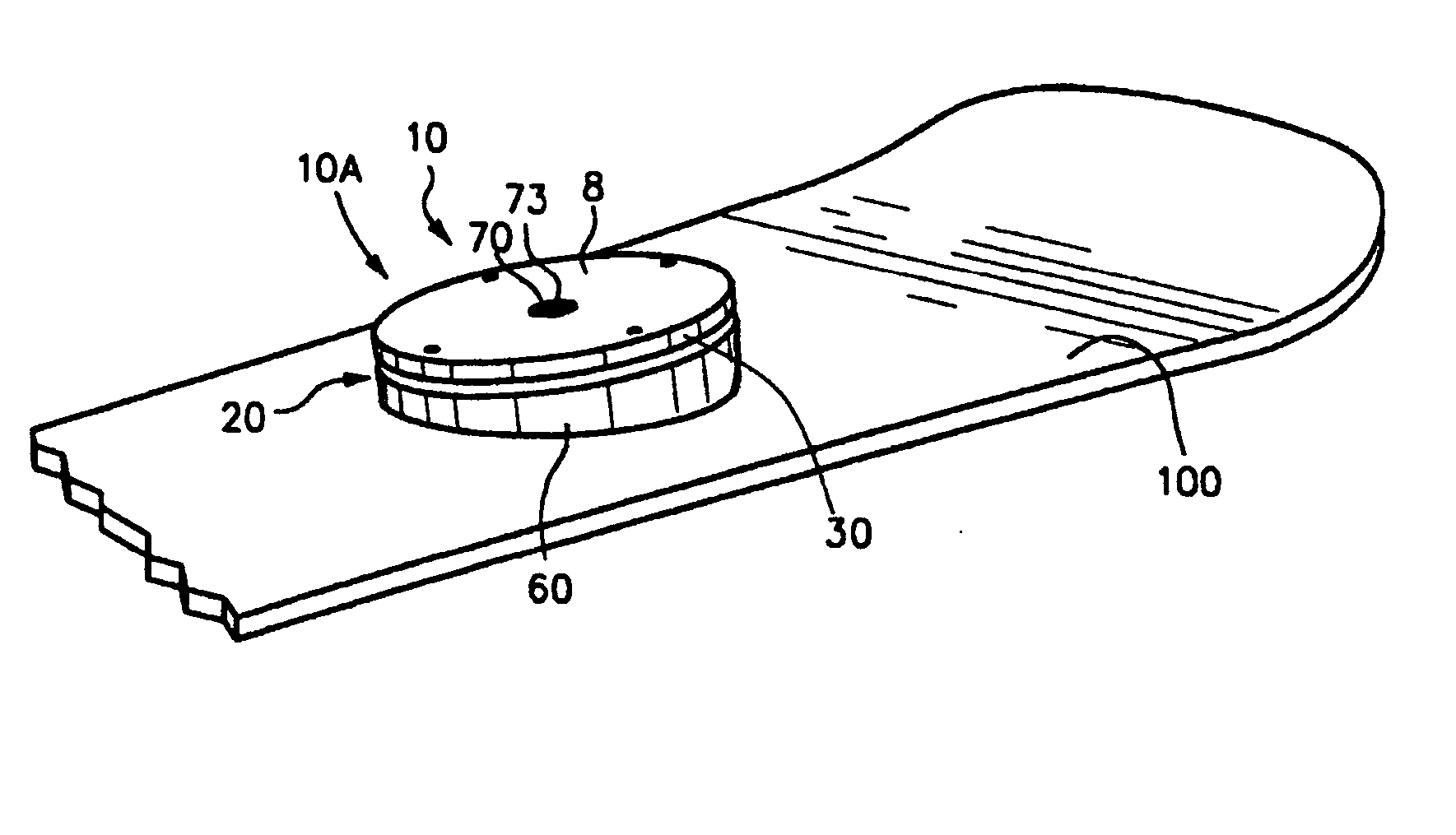
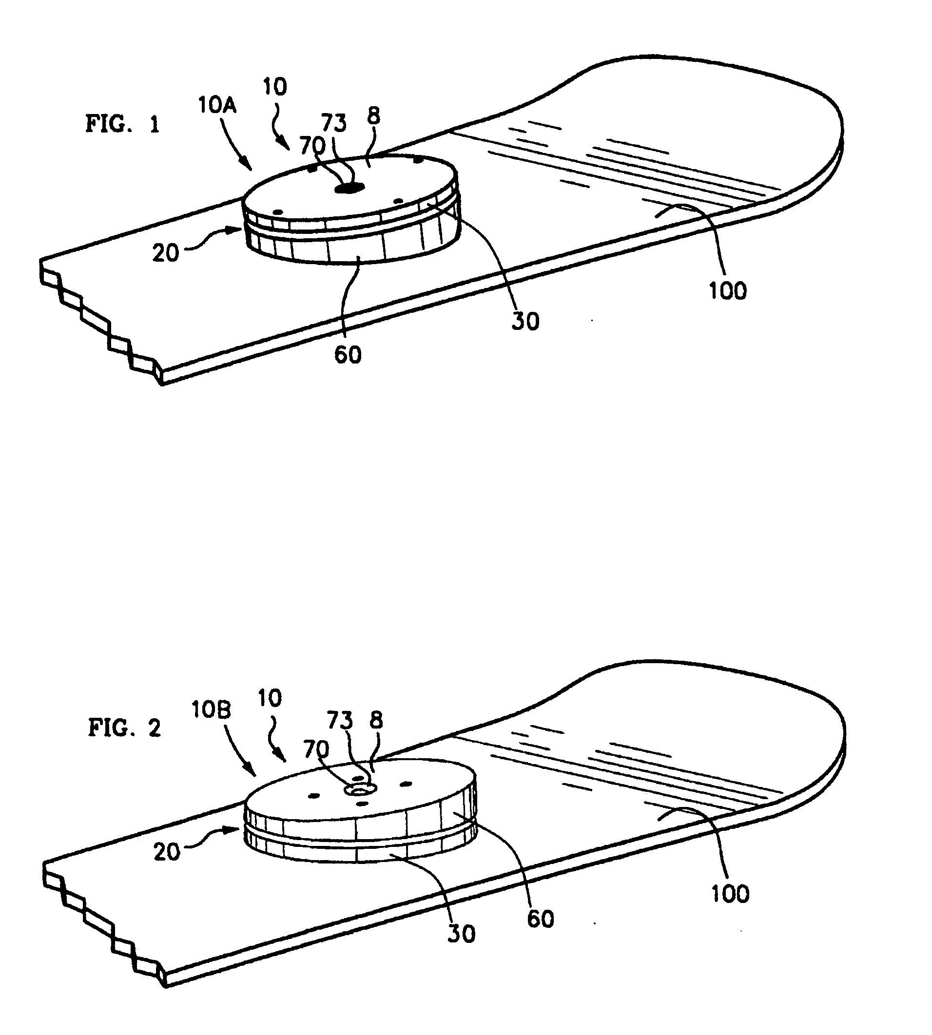
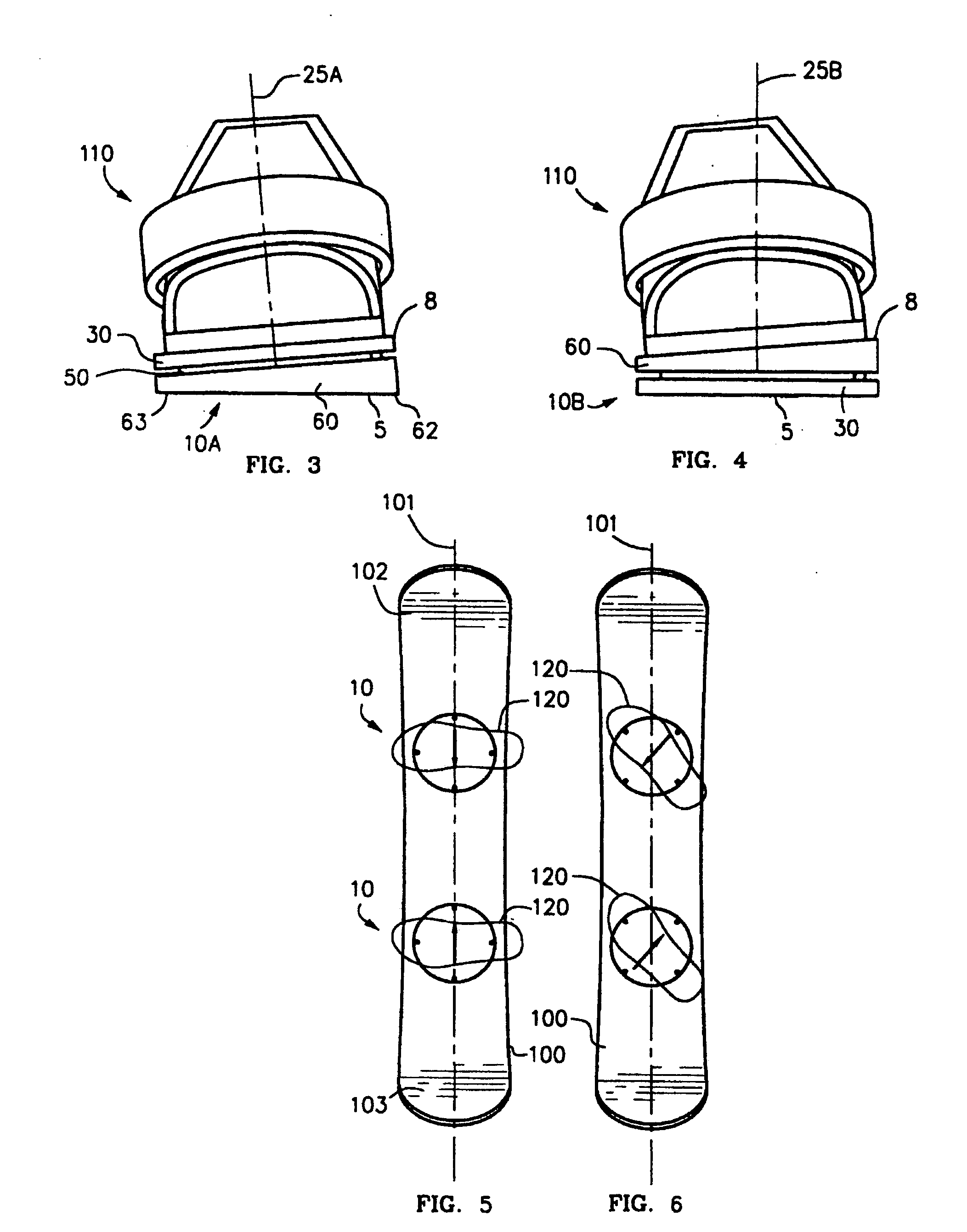
[0039]FIG. 3 is a back view of first embodiment of mount 10, mount 10A, with an exemplary binding 110 attached to upper surface 8. Mount 10A includes swivel assembly 20 comprised of cant disk 60 and plate 30, such that swivel assembly 20 has a swivel axis 25A that is not normal to the plane of snowboard 100 and generally parallel to the rider's leg when standing erect.

Example

[0040]FIG. 4 is a back view of second embodiment of mount 10, mount 10B, which includes cant disk 60 disposed above first plate 30, such that swivel assembly 20 has a swivel axis 25B that is normal to the plane of snowboard 100, and not normal to the mounting plane. Swivel axis 25B is not generally parallel to the rider's leg when standing erect.

[0041] First embodiment 10A and second embodiment 10B each provide the rider with a different riding behavior of snowboard 100, which may be understood with reference to FIG. 5.

[0042]FIG. 5 is a top view of a pair of mounts 10 attached to snowboard 100. The outlines of the rider's boots 120 are superimposed. The arrows indicate the orientation of the cant, pointing toward thinnest (lowest) part 63. Boots 120 are generally transverse snowboard 100 (perpendicular to longitudinal axis 101) and canted toward each other. This may be called a “neutral stance,” which the rider would use to move forward down a moderate slope. The rider's weight is...


PUM


Abstract

Mount 10 for attaching a boot binding 110 to a snowboard 100 allows free swiveling of binding 110 in a plane non-parallel to the deck of snowboard 100. Mount 10 includes a swivel assembly 20 with an upper face 8 for attaching a boot binding 120, a lower face 5 for attaching a snowboard, and cant disk 60 for canting boot binding 110 to an angle non-parallel to the deck of snowboard 100.

Description

CROSS-REFERENCE TO RELATED APPLICATION [0001] This application is a continuation-in-part of co-pending application Ser. No. 10 / 066,382; filed Feb. 1, 2002.FIELD OF THE INVENTION [0002] This invention relates to a mount for attaching boot bindings to a snowboard, and more particularly to a mount that allows the binding to swivel freely while lifting the binding at a comfortable cant angle. BACKGROUND OF THE INVENTION [0003] Snowboards are a type of sportboard used for sliding downhill on snow, propelled by gravity. Since about 1980, snowboards have evolved as hybrids of skis and skateboards. Skiers now share the hills and mountains equally with snowboarders. [0004] The typical snowboard in use in 2002 is similar to an enlarged skateboard with turned up ends, a smooth undersurface, and a symmetrical, slightly curved shape as that of an hourglass. There are no trucks or wheels, so the snowboard is steered by the rider by shifting his or her weight, causing the snowboard to flex slightl...

Claims


Application Information

Patent Timeline
IPC IPC(8): A63C9/00
CPCA63C10/18A63C10/14
Inventor FIEBING, JON
Owner FIEBING JON
Why Eureka
Try Eureka