Grounded electrical connector

Inactive Publication Date: 2005-03-03
HON HAI PRECISION IND CO LTD
View PDF6 Cites 11 Cited by
  • Summary
  • Abstract
  • Description
  • Claims
  • Application Information

AI Technical Summary

Problems solved by technology

However, there is no enough room inside the mated connector assembly for meeting the requirements of heat dissipation.
Whereas, such heightened shielding plate and contacts are readily warped during assembly and transportation of the

Method used


Image

  • Grounded electrical connector
  • Grounded electrical connector
  • Grounded electrical connector

Examples


Example

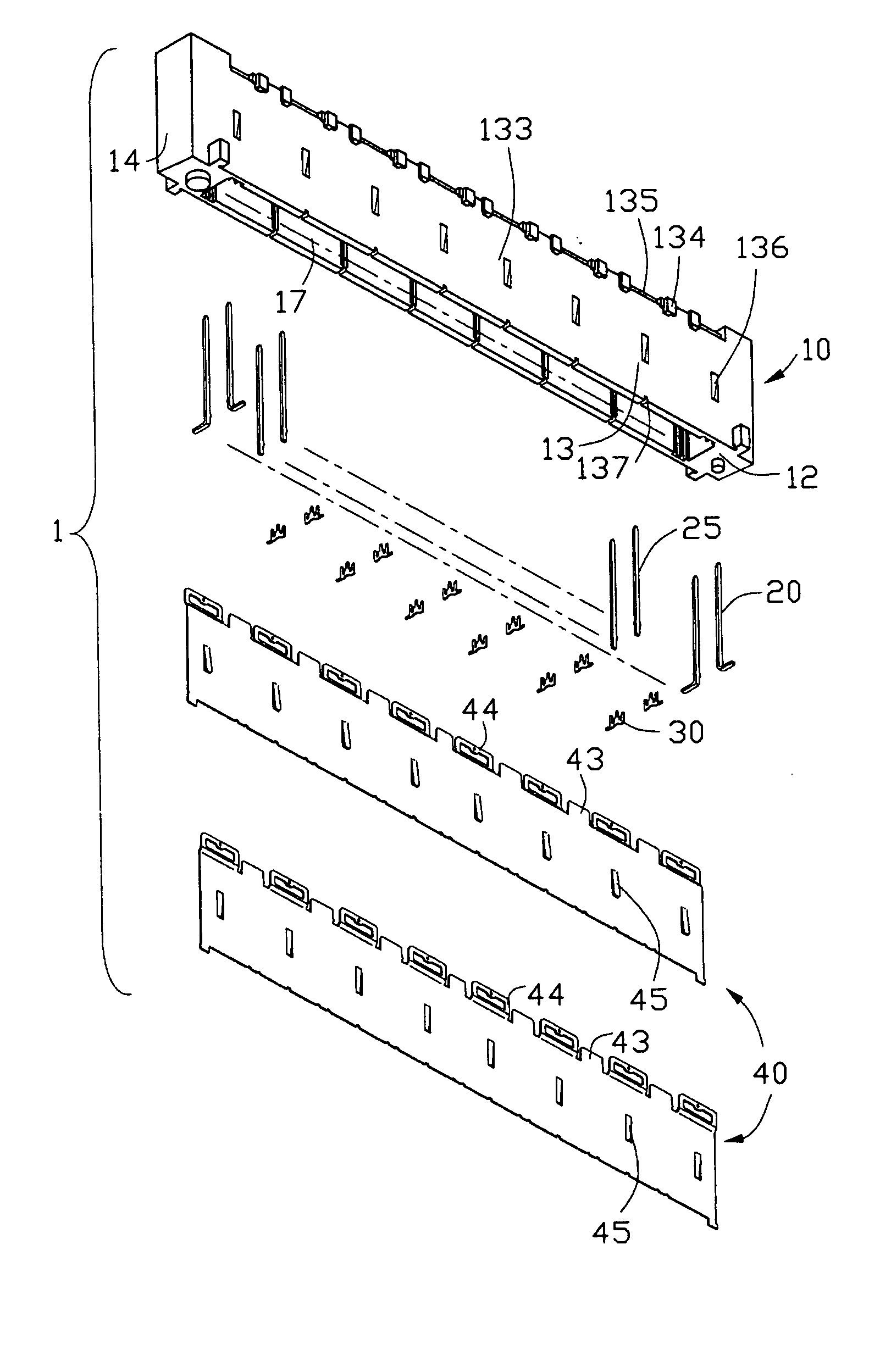
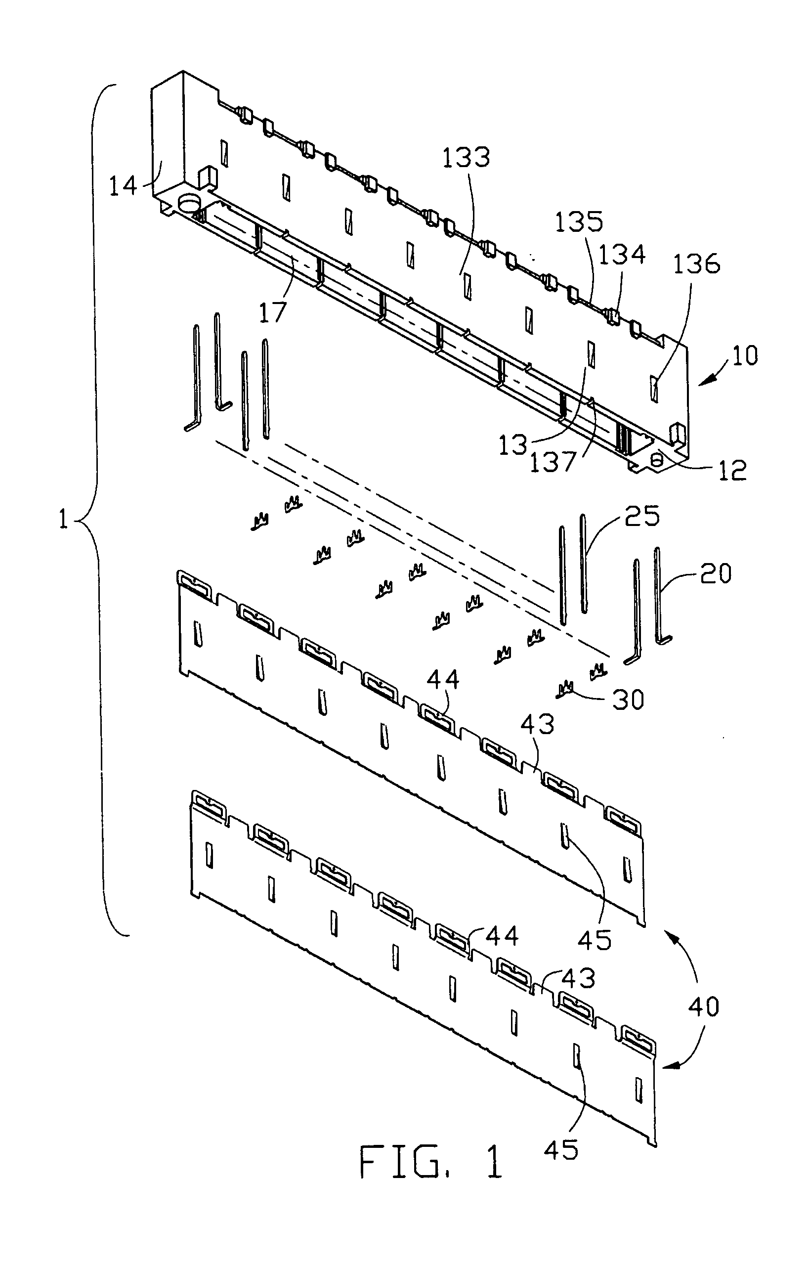
[0016] Referring to FIGS. 1 and 2, an electrical connector 1 in accordance with the present invention comprises an elongate dielectric housing 10, a plurality of signal terminals 20 and grounding terminals 25 received in the dielectric housing 10, respectively, a shielding member 40 attached to the dielectric housing 10 and a plurality of grounding members 30.

[0017] Referring to FIGS. 1 and 3, the dielectric housing 10 has a mating surface 11 and a mounting surface 12 opposite to the mating surface 11. Laterally spaced opposite side walls 13 and longitudinally spaced opposite end walls 14 extend between the mating surface 11 and the mounting surface 12, respectively. The dielectric housing 10 defines a mating space 16 in the mating surface 11 between the side walls 13 and a cavity 17 in the mounting surface 12 between the side walls 13. A clapboard 15 is formed between the mating space 16 and the cavity 17 and interconnects with the side walls 13 and the end walls 14. Each side wal...


PUM


Abstract

An electrical connector includes a dielectric housing defining a mating space with a pair of two opposite side wall by two sides thereof, a plurality of passageways formed in an inner face of each of the side walls, a number of signal and grounding terminals received in corresponding passageways, respectively, a shielding member attached to the side walls and a grounding member. Each grounding member includes an intermediate portion and three spaced beams extending from a side of the intermediate portion along a same direction. A middle one of the three beams is snugly retained in corresponding channel. The other two beams electrically and mechanically press the grounding terminal and the shield plate against the side wall, respectively.

Description

CROSS-REFERENCE TO RELATED APPLICATIONS [0001] Relevant subject matter is disclosed in a pending U.S. patent application Ser. No. 10 / 452,159, filed on May 30, 2003 and entitled “GROUNDED ELECTRICAL CONNECTOR”, which is invented by the same inventor as this patent application and assigned to the same assignee with this application.BACKGROUND OF THE INVENTION [0002] 1. Field of the Invention [0003] The present invention relates to an electrical connector, and particularly to a board-to-board connector with reliable grounding means. [0004] 2. Description of Related Art [0005] Board-to-Board connector assembly generally includes a plug and a receptacle connectors respectively mounted on two parallelly spaced printed circuit boards (PCB) and mated with each other for mechanical and electrical interconnection therebetween, whereby the corresponding printed circuit boards can be electrically connected with each other for signal transmission. [0006] A conventional board-to-board connector a...

Claims


Application Information

Patent Timeline
IPC IPC(8): H01R12/16H01R13/658
CPCH01R23/6873H01R13/65802H01R13/6582H01R12/00
Inventor PAN, WEI-HUA
Owner HON HAI PRECISION IND CO LTD
Why Eureka
Try Eureka