Cable connector

Active Publication Date: 2005-03-10
TYCO ELECTRONICS JAPAN GK
View PDF9 Cites 0 Cited by
  • Summary
  • Abstract
  • Description
  • Claims
  • Application Information

AI Technical Summary

Benefits of technology

[0006] To solve these and other problems, an exemplary embodiment of the present invention provides a cable connector which comprises contacts, a housing that accommodates these contacts, and a circuit board that is connected by soldering to the contacts and connected by soldering to the cable, and in which the contacts each have a contact part that contacts a mating contact on one end, and a soldering part that is attached by soldering to the circuit board on the other end, and the housing has a mating part that mates with a mating connector disposed on the front, and circuit board supporting parts that are used to support the circuit board and that extend rearward from both ends of the mating part, wherein locking arms that are locked with the mating connector, and that extend along both sides of the mating part and extend along the circuit board supporting parts, are disposed in the housing, and these locking arms have soldering parts that are attached by soldering to the circuit board.
[0006] To solve these and other problems, an exemplary embodiment of the present invention provides a cable connector which comprises contacts, a housing that accommodates these contacts, and a circuit board that is connected by soldering to the contacts and connected by soldering to the cable, and in which the contacts each have a contact part that contacts a mating contact on one end, and a soldering part that is attached by soldering to the circuit board on the other end, and the housing has a mating part that mates with a mating connector disposed on the front, and circuit board supporting parts that are used to support the circuit board and that extend rearward from both ends of the mating part, wherein locking arms that are locked with the mating connector, and that extend along both sides of the mating part and extend along the circuit board supporting parts, are disposed in the housing, and these locking arms have soldering parts that are attached by soldering to the circuit board.

Problems solved by technology

However, problems have been encountered in this conventional cable connector 101.

Method used


Image

  • Cable connector
  • Cable connector
  • Cable connector

Examples


Embodiment Construction

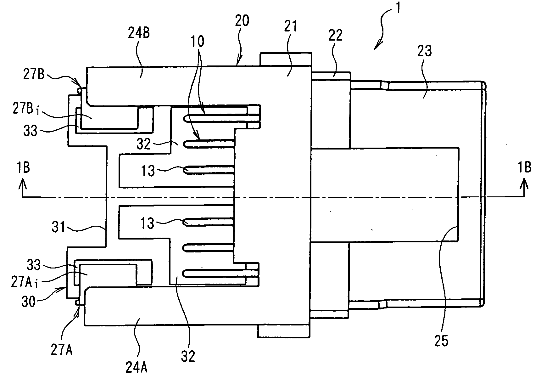
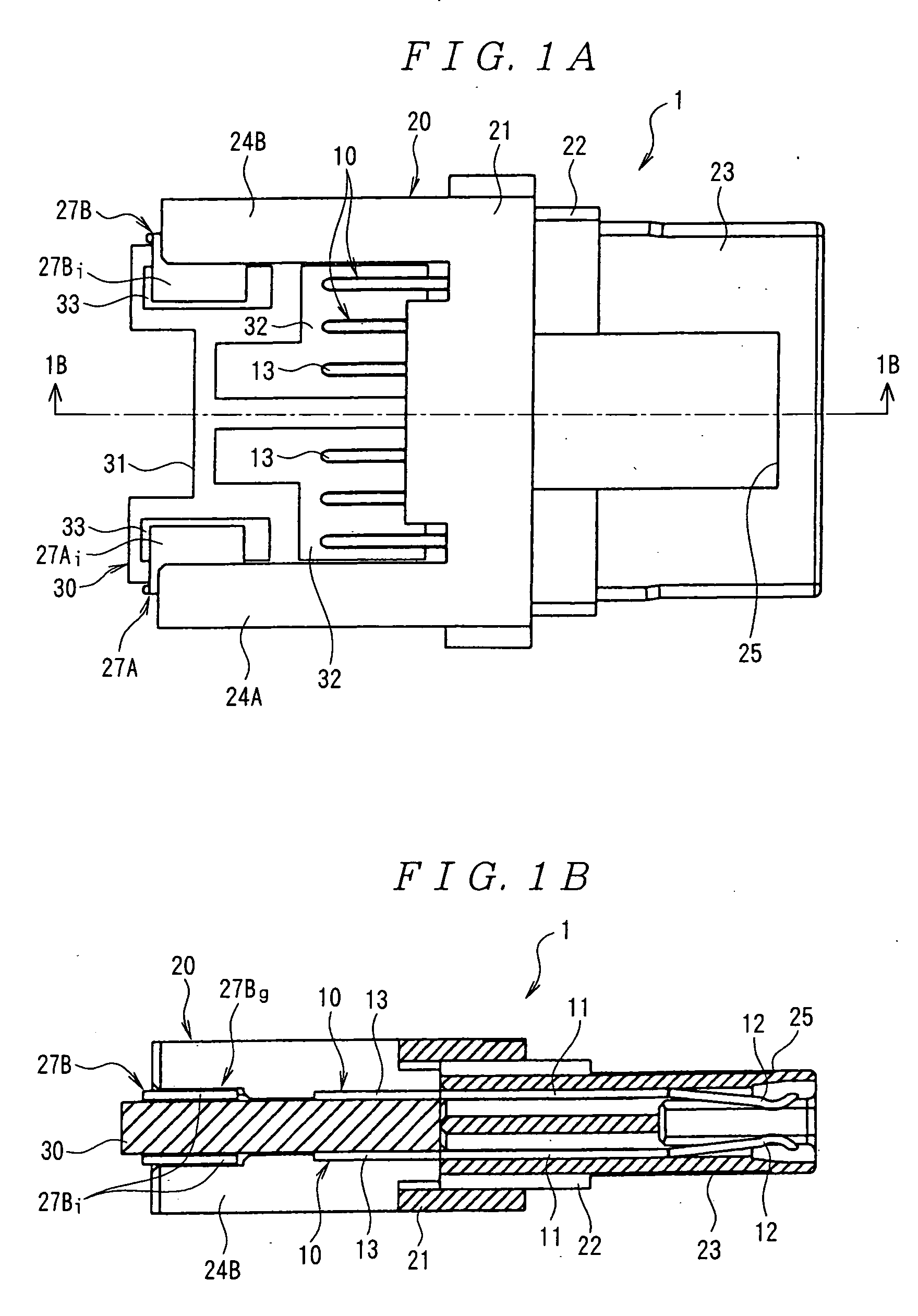
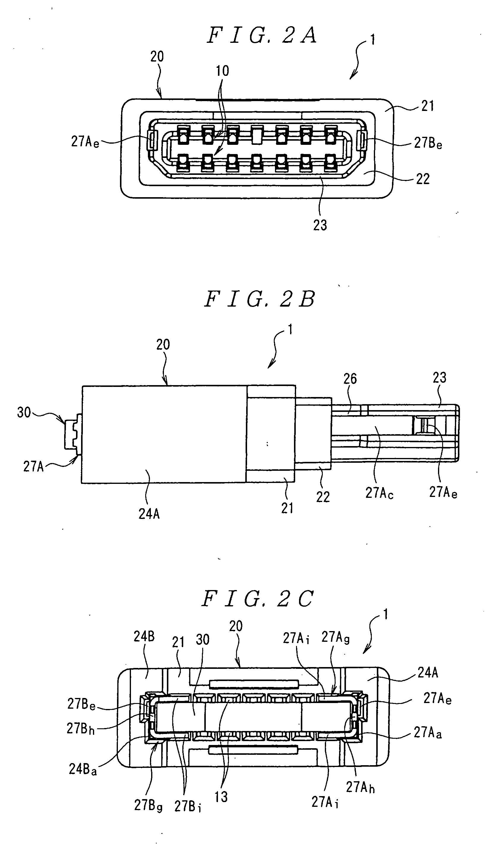
[0018] Next, an embodiment of the present invention will be described with reference to the figures. In FIGS. 1A and 1B, and 2A to 2C, the cable connector 1 comprises a plurality of contacts 10, a housing 20 that accommodates the contacts 10, a circuit board 30 that is soldered to the contacts 10 and soldered to a cable40 (see FIGS. 8A and 8B), and a pair of left and right locking arms 27A and 27B that are locked to the mating connector (not shown in the figures). This cable connector 1 may be used, for example, in the direct-current power supply of a digital camera.

[0019] As shown in FIGS. 1A and 1B, and 3A and 3B, each contact 10 comprises a fastening part 11 that is press-fitted to the housing 20, a contact part 12 that extends forward (i.e., to the right in FIG. 1B) from the fastening part 11 and contacts a mating contact (not shown in the figures), and a soldering part 13 that extends rearward from the fastening part 11 and is soldered to the circuit board 30. The respective c...


PUM


Abstract

The present invention provides a cable connector that can reduce the stress that is generated in the solder connections between the contacts of the connector and the circuit board. The cable connector comprises a plurality of contacts, each having a contact part configured to contact a mating contact on one end, and a soldering part on the other end, a circuit board that is soldered to the soldering part of the contacts and is soldered to a cable, a housing that accommodates the contacts, the housing having a mating part disposed on the front thereof configured to mate with the mating connector and circuit board supporting parts that support the circuit board and extend rearward from both ends of the mating part, and locking arms disposed in the housing and configured to lock with a mating connector. The locking arms extend along both sides of the mating part and extend along the circuit board supporting parts.

Description

FIELD OF THE INVENTION [0001] The present invention relates to a cable connector used in electrical or electronic devices such as portable telephones and digital cameras. BACKGROUND OF THE INVENTION [0002] An exemplary cable connector 101, shown in FIGS. 11A to 11C, is known (see U.S. Pat. No. 5,766,027). As is shown in FIG. 11A, this cable connector 101 comprises a plurality of contacts 110, a housing 120 that accommodates the plurality of contacts 110, a circuit board 130 that is soldered to the respective contacts 110 and soldered to a conductor 161 of a cable 160. A metal shell 140 covers the housing 120. Each contact 110 has a contact part 111 that contacts a mating contact on one end (the end on the side that mates with the mating connector), and has a soldering part 112 that is soldered to the circuit board 130 on the other end. [0003] Moreover, as is shown in FIGS. 11A, 11B and 11C, the housing 120 comprises a mating part 121 disposed on the front side (i.e., on the left sid...

Claims


Application Information

Patent Timeline
IPC IPC(8): H01R12/71H01R13/639H01R13/627H01R13/66
CPCH01R13/6658H01R13/6275H01R13/639
Inventor SASAME, NAOTAKATSUJI, JUNYAKAJINUMA, SHUJI
Owner TYCO ELECTRONICS JAPAN GK
Why Eureka
Try Eureka