Plasma display panel

a technology of display panel and plasma, which is applied in the direction of gas discharge electrodes, gas discharge vessels/containers, gas discharge tubes, etc., can solve the problems of small phosphor covering area, poor discharge characteristic, and still image implementation that is not smoothly diagonally implemented, so as to improve efficiency and contrast ratio, high-speed driving

Inactive Publication Date: 2005-03-31
LG ELECTRONICS INC
View PDF1 Cites 6 Cited by
  • Summary
  • Abstract
  • Description
  • Claims
  • Application Information

AI Technical Summary

Benefits of technology

[0016] According to the present invention, brightness, efficiency and the contrast ratio are improved and high-speed driving is accomplished.

Problems solved by technology

The stripe type structure shown in FIG. 1 has a good discharge characteristic, but has a disadvantage that the phosphor covering area is small.
The well type structure shown in FIG. 2 has high brightness since the covering area of phosphors is wide, but has a problem that the discharge characteristic is bad.
Therefore, upon implementation of a still image, the still image is not implemented smoothly diagonally.
Thus, there is a problem in that the picture quality is degraded.

Method used


Image

  • Plasma display panel
  • Plasma display panel
  • Plasma display panel

Examples


first embodiment

[0027] First Embodiment

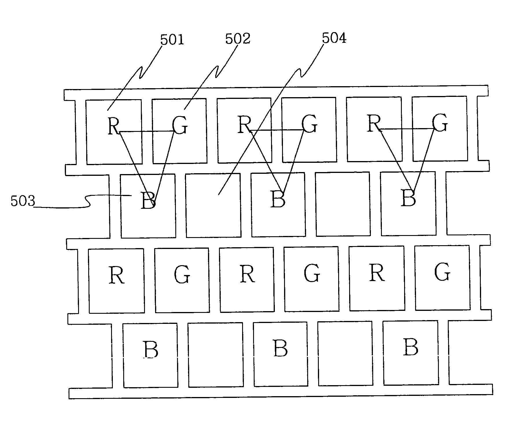
[0028] According to a first embodiment of the present invention, there is provided a plasma display panel in which square cells constitute a delta type barrier rib structure, wherein a red cell and a green cell are alternately formed in a first horizontal cell line of the cells, a blue cell is located at the lower center between the red cell and the green cell in a second horizontal cell line of the cells, the blue cell is alternately formed together with a blink cell, and the first horizontal cell line and the second horizontal cell line are alternately formed in the vertical direction.

[0029] The red cell, the green cell and the blue cell constitute one picture element in an inverted triangle shape, and the picture element is parallel to the direction vertical to the horizontal direction.

[0030] Transparent electrodes are formed on the cells in the horizontal direction, bus electrodes are formed at the bottom of the transparent electrodes, and data electrode...


PUM


Abstract

The present invention relates to a plasma display panel, and more particularly, to a cell structure of a plasma display panel. In a plasma display panel in which square cells constitute a delta type barrier rib structure, a red cell and a green cell are alternately formed in a first horizontal cell line of the cells, a blue cell is located at the lower center between the red cell and the green cell in a second horizontal cell line of the cells, the blue cell is alternately formed together with a blank cell, and the first horizontal cell line and the second horizontal cell line are alternately formed in the vertical direction. Accordingly, brightness, efficiency and the contrast ratio are improved and high-speed driving is accomplished.

Description

[0001] This Nonprovisional application claims priority under 35 U.S.C. § 119(a) on Patent Application No. 10-2003-066612 filed in Korea on Sep. 25, 2003, the entire contents of which are hereby incorporated by reference. BACKGROUND OF THE INVENTION [0002] 1. Field of the Invention [0003] The present invention relates to a plasma display panel, and more particularly, to the cell structure of a plasma display panel. [0004] 2. Description of the Background Art [0005]FIG. 1 illustrates a stripe type barrier rib structure of a conventional plasma display panel. FIG. 2 illustrates a well type barrier rib structure of a conventional plasma display panel. [0006] The stripe type structure shown in FIG. 1 has a good discharge characteristic, but has a disadvantage that the phosphor covering area is small. The well type structure shown in FIG. 2 has high brightness since the covering area of phosphors is wide, but has a problem that the discharge characteristic is bad. [0007]FIG. 3 illustrates...

Claims


Application Information

Patent Timeline
Patent Type & Authority Applications(United States)
IPC IPC(8): H01J11/24H01J11/36H01J11/44
CPCH01J11/12H01J2211/444H01J2211/365H01J11/36H01J11/20H01J11/44
Inventor MIN, BYOUNG KUK
Owner LG ELECTRONICS INC
Why Eureka
Try Eureka