

Whistle with light emitting device
a light-emitting device and whistle technology, applied in the field of whistle, can solve the problems of the pepper gas spray itself and the stun gun being dangerous for children
- Summary
- Abstract
- Description
- Claims
- Application Information
AI Technical Summary
Problems solved by technology
Method used
Image

Examples
Embodiment Construction
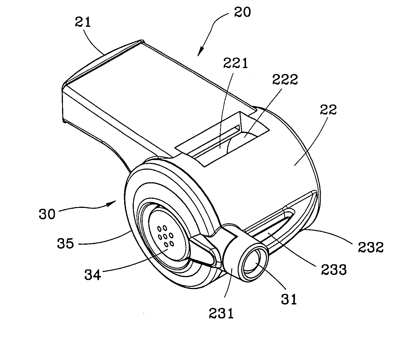
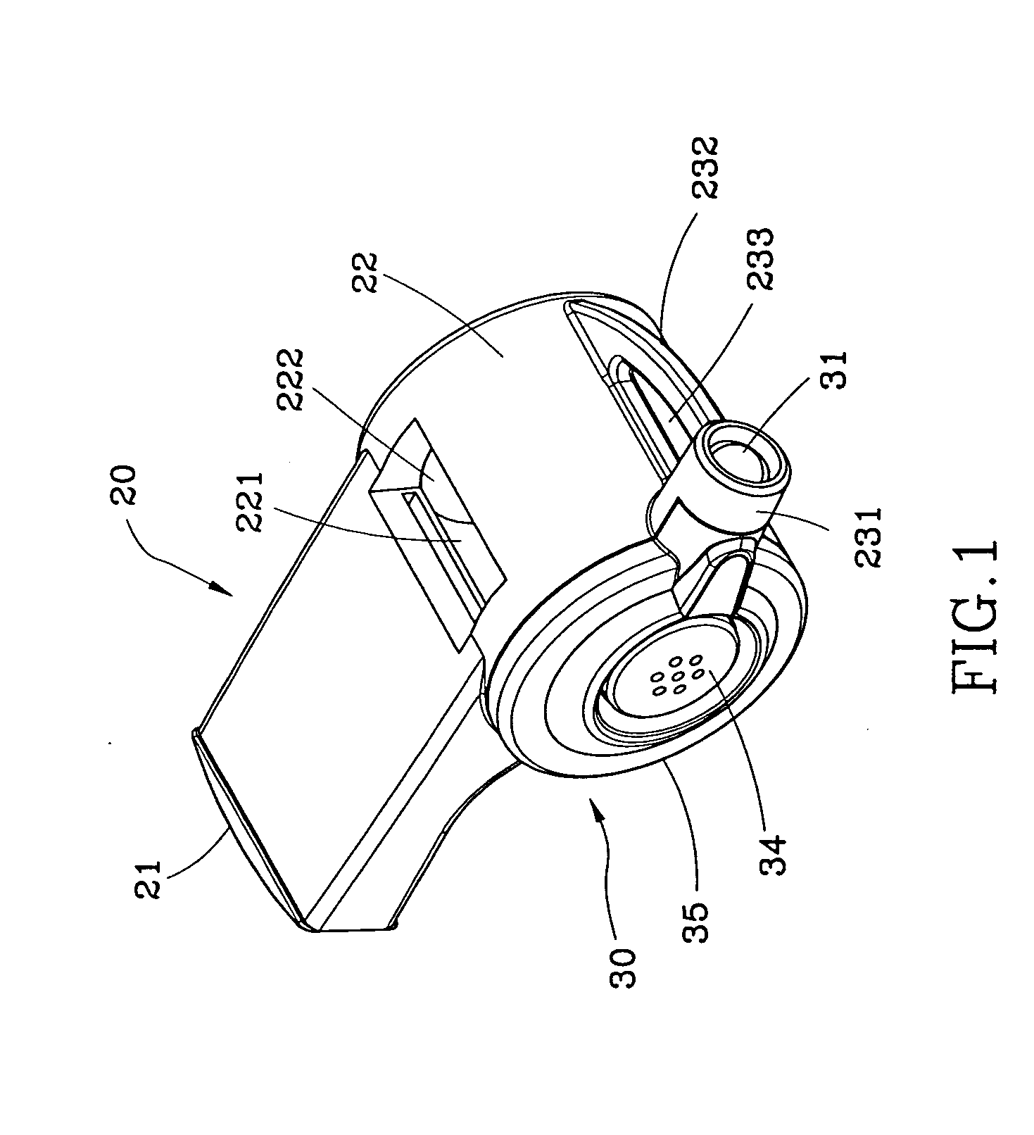
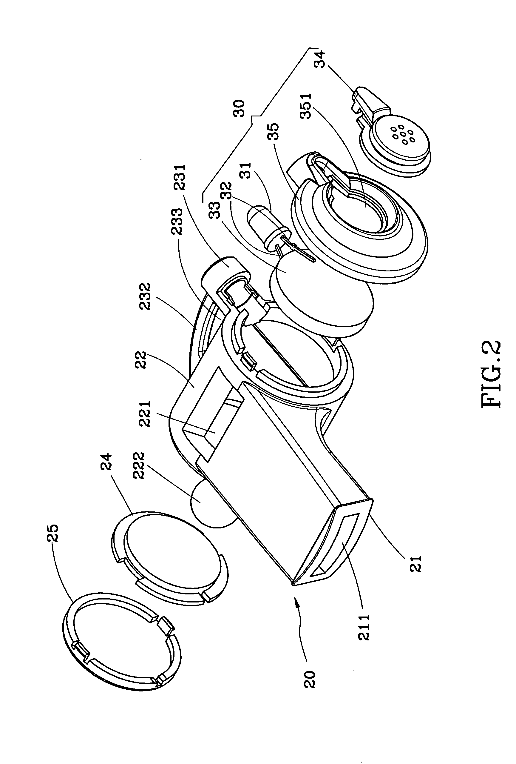
[0009] As shown in FIG. 1 and FIG. 2, a whistle 20 of the preferred embodiment of the present invention comprises:
[0010] A whistle member 20 has a mouthpiece 21 at a front thereof, a chamber 22 therein, a passage 211 in the mouthpiece 21 and communicated with the chamber 22, an outlet 221 on a sidewall of the chamber 22 and a ball received in the chamber 22. The chamber 22 is open at opposite lateral sides and at the left open of which is an annular rib at a periphery thereof to form a recess 23 therewithin. A tube 231 is provided on the whistle member 20 having an end communicated with the recess 23. The whistle member 20 is provided with a hanger 232 at a rear thereof, wherein the hanger 232 has opposite ends connected with the rear of the whistle member 20 and the tube 231. Between the hanger 232 and the whistle member 20 is an opening for tying a rope (not shown). A round board is provided at the right open of the chamber 22 to seal it and a cover 25 is detachably provided on t...
PUM
 Abstract
Description
Claims
Application Information