Orthodontic bracket and arch wire

a technology which is applied in the field of orthodontic brackets and arch wires, can solve the problems of large friction and poor slippage, insufficient torque, and orthodontic brackets that are easy to disengage from the tooth surfa

Inactive Publication Date: 2005-03-31
CHIKAMI MIRUTETABUKU
View PDF6 Cites 61 Cited by
  • Summary
  • Abstract
  • Description
  • Claims
  • Application Information

AI Technical Summary

Problems solved by technology

The orthodontic bracket 20 illustrated in FIG. 17 has a problem that the arch wire 30 and the bottom of the orthodontic bracket 20 are in surface contact with each other, resulting in large friction and poor slippage.
Furthermore, there is a problem that when an arch wire having an outer shape not complementary to the inside space of the orthodontic bracket 20 illustrated in FIG. 17 is applied to the orthodontic bracket, there will be a play space of the arch wire within the inside space of the orthodontic bracket.
Therefore, in producing a torque by twisting the arch wire, the torque can not be sufficiently produced even if the arch wire is ligatured by a ligaturing wire or module.
Further, the conventional orthodontic bracket has a problem that the orthodontic bracket is easily disengaged from the tooth surface since the bonding surface contacting the tooth surface has a flat shape.
Therefore, when the arch wire is used in early stages of treatment where the teeth irregularity has not been corrected, the arch wire may experience excessive bending stresses and get deformed since the arch wire can not sufficiently follow large bending, which may result in degraded elasticity of the arch wire or breakage of the arch wire.

Method used


Image

  • Orthodontic bracket and arch wire
  • Orthodontic bracket and arch wire
  • Orthodontic bracket and arch wire

Examples


embodiment 1

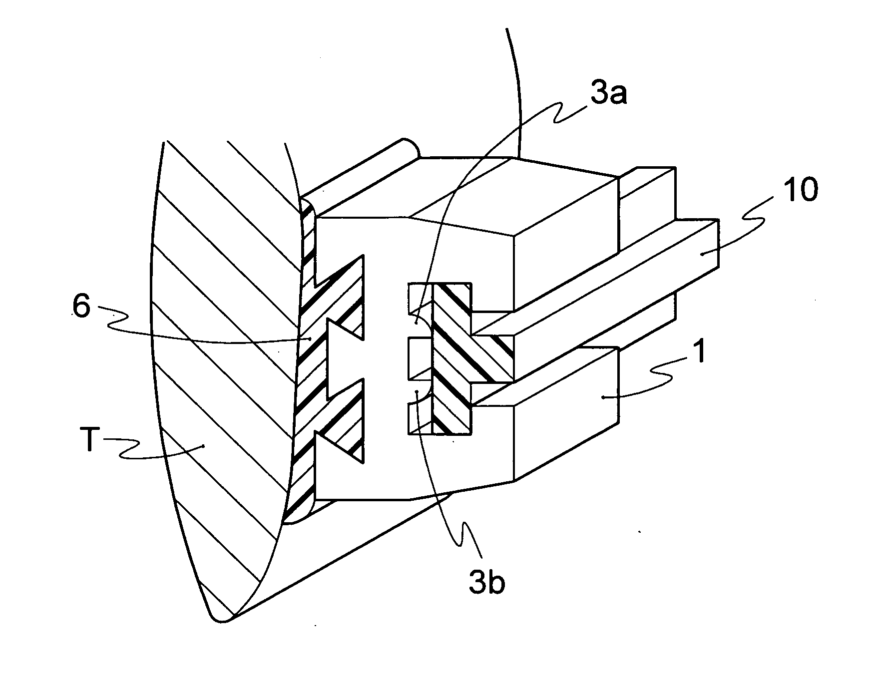
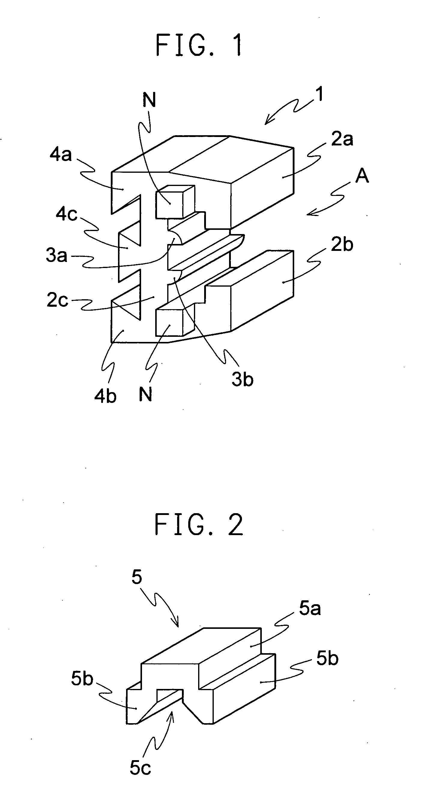
[0067] An orthodontic bracket (hereinafter, referred to as “bracket”) 1 illustrated in FIG. 1 includes a base 2c which is secured to a tooth T (see, FIG. 3) and claws 2a, 2b having a L-shape cross section, which are protruded from the upper and lower ends of the base 2c such that they are faced to each other. The base 2c and the claws 2a, 2b constitute a wire engaging slot A having a T-shape cross section. Fixed spacers 3a, 3b are provided on the bottom of the wire engaging slot A (namely, the portion of the base 2c which lies between the claws 2a, 2b). The bracket 1 is made of the same material as that of the aforementioned conventional bracket.

[0068] Referring to FIG. 1, the fixed spacers 3a, 3b are shown as continuous line-shaped (or protruded strip) protrusions, however, they are not limited to this configuration and may be configured from combinations of several pillars or pillars and protruded strips.

[0069] The “line-shaped protrusions” provided on the inside bottom of the b...

embodiment 2

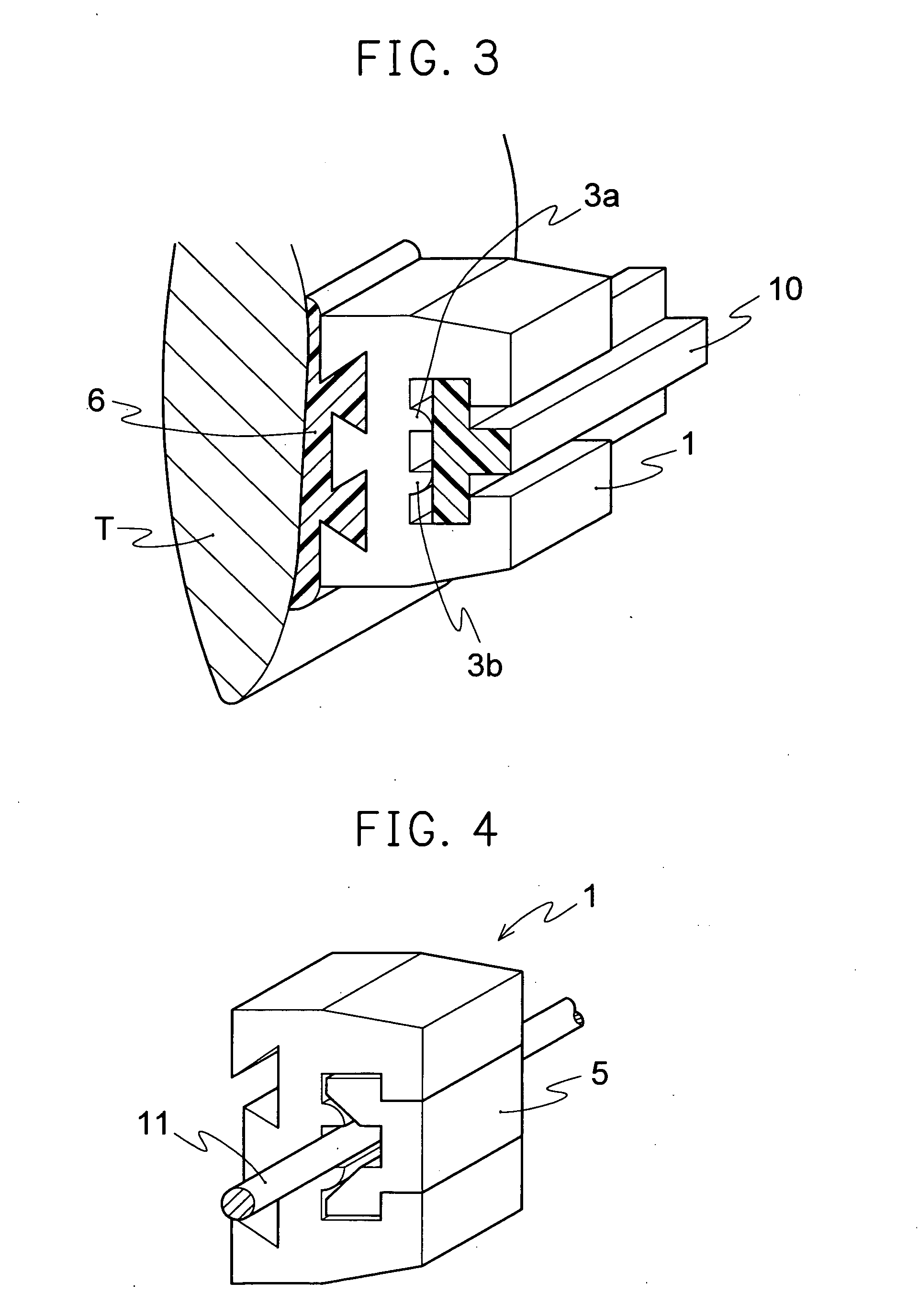
[0071] According to the present embodiment, as illustrated in FIGS. 4 and 5, a movable spacer 5 including two legs 5b, 5b and a coupling portion 5a coupling the two legs 5b, 5b is movably inserted through the above engaging slot A. As illustrated in FIGS. 4 and 5, when the movable spacer 5 is inserted into the engaging slot A, the movable spacer is placed in the engaging slot such that the two legs 5b, 5b straddle the fixed spacers 3a, 3b and at least the outer surfaces of the legs 5b, 5b are in contact with the inside surfaces of the claws 2a, 2b of the bracket (see FIGS. 4 and 5). In other words, preferably, the gap between the tip ends of the above two claws 2a, 2b is blocked with the coupling portion 5a, and the space between the root portions of the claws 2a, 2b other than the fixed spacers 3a, 3b and the arch wire is substantially blocked with the legs 5b, 5b (namely, almost all the space other than the space required for inserting an arch wire having a round or rectangular cr...

embodiment 3

[0076] As illustrated in FIG. 11, the bracket of the present embodiment has undercuts constituted by two legs 4a, 4b each having a substantially dovetail cross section and formed at the position which is faced to the surface of a tooth. The undercuts may have curved surfaces such as partial cylindrical surfaces as illustrated in FIG. 13 or elliptic surfaces, instead of the tapered surfaces of the legs 4a, 4b having a dovetail cross section of FIG. 11. Also, an additional leg 4c having a dovetail cross section may be provided between the legs 4a, 4b having a dovetail cross section (see FIG. 12). The number of the additional leg 4c having a dovetail cross section may be one or more than one. Also, as illustrated in FIG. 14, the undercuts may be formed from rectangular cylinders 4a, 4b and a member 4c formed from a combination of a rectangular cylinder and a substantially elliptic cylinder or circular cylinder.

[0077] The undercuts allows the bracket to have a cuneiform physical bondin...


PUM


Abstract

An orthodontic bracket of the present invention is an orthodontic bracket to be attached through adhesive to an individual tooth in an alignment of teeth including a tooth to be corrected comprising two claws faced to each other, the two claws forming therebetween an engaging slot for engaging an arch wire and the engaging slot having a T-shaped cross section, and a fixed spacer provided on the bottom of the engaging slot.

Description

CROSS-REFERENCE TO RELATED APPLICATION [0001] This is a continuation-in-part of PCT international application No. PCT / JP2003 / 015578 filed on Dec. 5, 2003 incorporated herein by reference.TECHNICAL FIELD [0002] The present invention relates to orthodontic brackets and arch wires, and more particularly to orthodontic brackets including fixed spacers formed at least on the bottom of an engaging slot and arch wires including a waveform curved surface formed at the portion which, when inserted into such brackets, contacts the inside surface of the bracket. BACKGROUND ART [0003] The present inventors have previously proposed an orthodontic bracket 20 which is secured to the surface of a tooth T by adhesive 40 as illustrated in FIG. 17 (See, for example, U.S. Pat. No. 5,474,447 (FIGS. 1 to 6 in the third and forth boxes)). [0004] The orthodontic bracket 20 illustrated in FIG. 17 has a substantially C-shape cross section. An arch wire 30 having an outer shape complementary to the shape of t...

Claims


Application Information

Patent Timeline
Patent Type & Authority Applications(United States)
IPC IPC(8): A61C7/20A61C7/28A61C7/30
CPCA61C7/20A61C7/30A61C7/287
Inventor CHIKAMI, KUNIO
Owner CHIKAMI MIRUTETABUKU
Why Eureka
Try Eureka