
Self Ligating Orthodontic Bracket System Employing Brackets Having Rotatable Members

a self-ligating, bracket technology, applied in the field of self-ligating orthodontic bracket system, can solve the problem that the archwire cannot be easily removed from the bracket slot, and achieve the effect of low cost, easy production and industrial scal

Inactive Publication Date: 2013-11-21
RMO INC
View PDF5 Cites 33 Cited by
  • Summary
  • Abstract
  • Description
  • Claims
  • Application Information

AI Technical Summary

Benefits of technology

The patent text describes a bracket system for dental applications that includes a cylindrical recess and a rotatable member that can be securely positioned within the recess. The recess and member have interlocking elements that prevent free rotation of the member, and can be rotated in both directions. The bracket is fixed to a tooth surface using a bracket bonding pad. The technical effect of this system is the ability to securely position a bracket on a tooth surface and provide a stable and secure attachment for orthodontic brackets.

Problems solved by technology

In particular, such extensions, when rotated to occlude at least a portion of the slot opening thereby preventing an archwire residing in the bracket slot from exiting therefrom, and when rotated out of the slot opening, these extensions do not prevent the archwire from being readily removed from the bracket slot, e.g., by an orthodontist or technician.

Method used


Image

  • Self Ligating Orthodontic Bracket System Employing Brackets Having Rotatable Members
  • Self Ligating Orthodontic Bracket System Employing Brackets Having Rotatable Members
  • Self Ligating Orthodontic Bracket System Employing Brackets Having Rotatable Members

Examples


Embodiment Construction

is given with reference to the figures which depict:

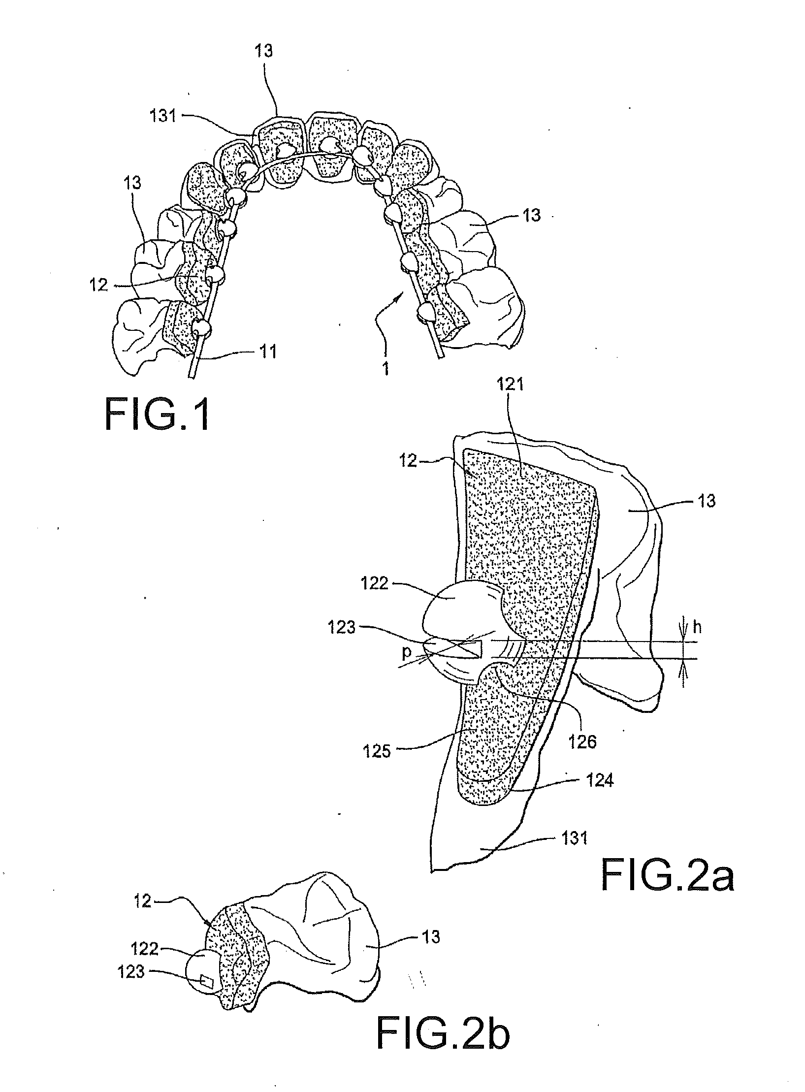
[0062]FIG. 1: a view, from the inside of the mouth, of a lingual orthodontic appliance on a dental arch of a patient,

[0063]FIG. 2a: a perspective depiction of a bracket according to the invention attached to a surface of a tooth,

[0064]FIG. 2b: a perspective depiction of a bracket according to the invention attached to a surface of a tooth, and comprising a tube,

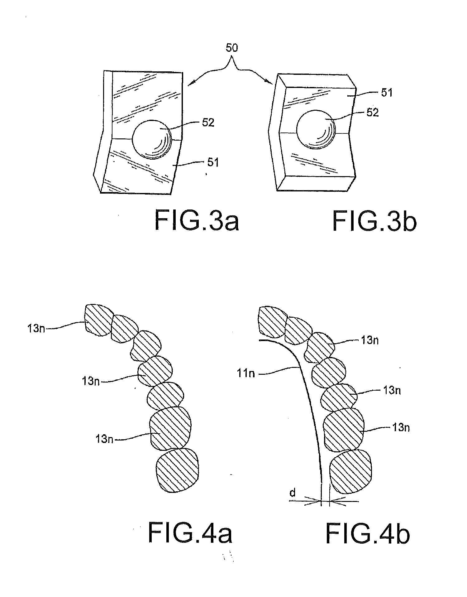
[0065]FIG. 3a: a perspective view of a first example of a blank for producing a bracket according to the invention,

[0066]FIG. 3b: a perspective view of a second example of a blank for producing a bracket according to the invention,

[0067]FIG. 4a: an illustration of a numerical representation of a cross section of a dental arch in a plane of the orthodontic archwire,

[0068]FIG. 4b: an illustration of a numerical representation of the positioning of an orthodontic archwire for a cross section of a dental arch in a plane of the orthodontic archwire, after a second step of the met...


PUM

PropertyMeasurementUnit
Fractionaaaaaaaaaa
Thicknessaaaaaaaaaa
Volumeaaaaaaaaaa

Abstract

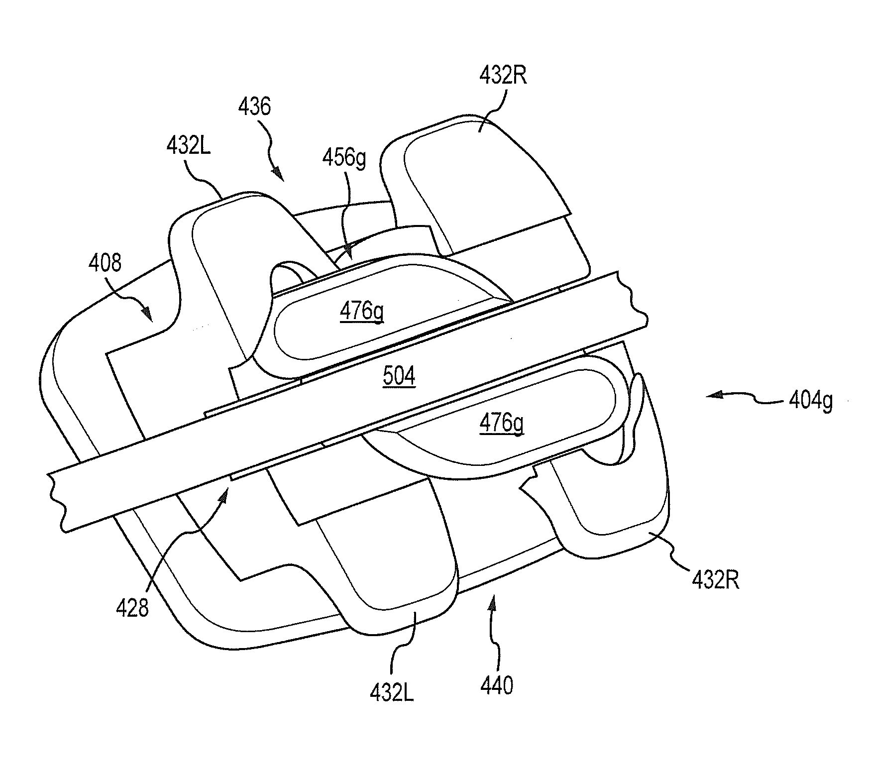
The present disclosure is directed, at least in part, to a self ligating orthodontic bracket system that includes a rotatable member for securing an archwire within a slot of a bracket. Embodiments of the orthodontic bracket system disclosed herein include a bracket body containing the archwire slot as well as tie wings for attaching various orthodontic devices (e.g., elastomeric bands) to the bracket. The rotatable member is rotatable in a first direction (e.g., counter clockwise) relative to a body of the bracket for securing or locking the archwire within the slot, and for rotating in an opposite direction (e.g., a clockwise direction) relative to the bracket body for unsecuring or unlocking the archwire so that it is substantially unrestrained from exiting the slot. Other embodiments include an orthodontic appliance and method of producing and using the same, and preferably employed in a lingual orthodontic system, that includes friction reducing features between an interior of an archwire slot portion of the appliance and an archwire placed within the archwire slot.

Description

REFERENCE TO RELATED APPLICATIONS[0001]This application is a continuation-in-part application to and claims priority to U.S. patent application Ser. No. 13 / 117,085, filed May 26, 2011, which claims priority to U.S. Provisional Patent Application No. 61 / 518,927, filed May 12, 2011; both of which are incorporated fully herein by this reference. This application is also a continuation-in-part application of U.S. patent application Ser. No. 12 / 937,588 filed on Apr. 3, 2009; this application is a continuation-in-part of pending U.S. patent application Ser. No. 13 / 595,548, filed Aug. 27, 2012, which is a continuation of U.S. patent application Ser. No. 11 / 852,057, filed Sep. 7, 2007 (now issued U.S. Pat. No. 8,251,697), and claims the benefit of U.S. Provisional Application No. 60 / 824,891 filed on Sep. 7, 2006; this application also seeks priority from U.S. patent application Ser. No. 12 / 724,159, filed Mar. 15, 2010, which claims the benefit of U.S. Provisional Patent Application Ser. No....

Claims


Application Information

Patent Timeline
IPC IPC(8): A61C7/28A61C7/00
CPCA61C7/285A61C7/002A61C7/143A61C7/28A61C7/145A61C7/146A61C13/0022Y10T29/49568
Inventor SMITH, JEFFREY ALLENTRINH, NAMDUPRAY, DENNISGUALANO, CHRISTOPHELAUB, LEON W.MACCHI, ALDO
Owner RMO INC
Learn More