Dual stage current limiting surge protector system

Inactive Publication Date: 2005-04-07
ILLINOIS TOOL WORKS INC
View PDF16 Cites 3 Cited by
  • Summary
  • Abstract
  • Description
  • Claims
  • Application Information

AI Technical Summary

Benefits of technology

[0014] Accordingly, it is a general object of the present invention to provide a dual stage current limiting surge protector system for pr

Problems solved by technology

As is generally well-known to those skilled in the telecommunications industry, modern telecommunications equipment is susceptible to transient surges such as those caused by lightning strikes and other voltage surges on the transmis

Method used


Image

  • Dual stage current limiting surge protector system
  • Dual stage current limiting surge protector system
  • Dual stage current limiting surge protector system

Examples


Embodiment Construction

[0023] It is to be distinctly understood at the outset that the present invention shown in the drawings and described in detail in conjunction with the preferred embodiments is not intended to serve as a limitation upon the scope or teachings thereof, but is to be considered merely as an exemplification of the principles of the present invention.

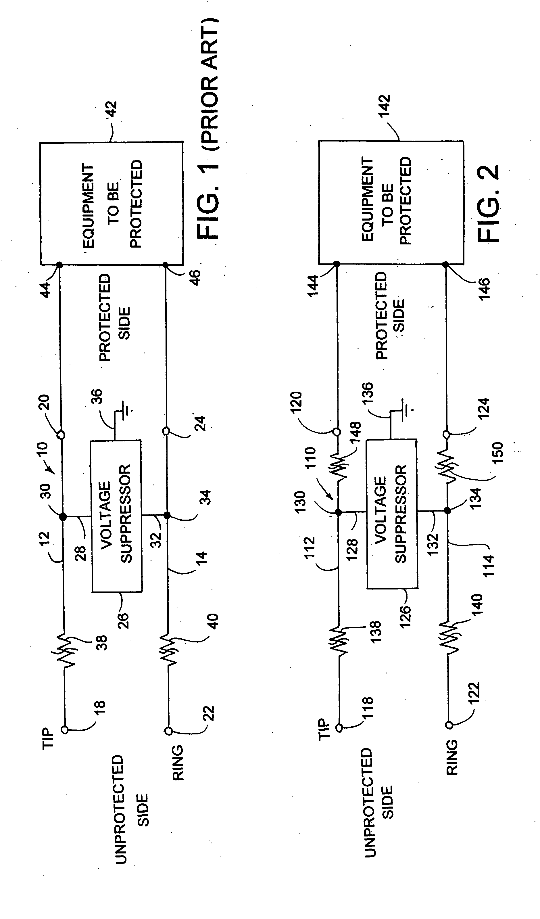
[0024] Referring now in detail to the drawings, there is illustrated in FIG. 1 a schematic system diagram of a prior art surge protector 10 for protecting telecommunications equipment from power and transient surges occurring on tip and / or ring conductors of transmission lines connected thereto. The surge protector circuit 10 is comprised of first and second data signal conductors 12 and 14. One end of the first conductor 12 is coupled to an input tip terminal pin 18 and its other end thereof is coupled to an output tip terminal pin 20. Similarly, one end of the second conductor 14 is coupled to an input ring terminal pin 22 and its other e...


PUM


Abstract

A dual stage current limiting surge protector system for protecting telecommunications equipment from power and surge transients is provided. The surge protector system includes a voltage suppressor having first and second ends operatively coupled between input tip and ring terminal pins. The first and second ends of the voltage suppressor are also operatively coupled between output tip and ring terminal pins. First and second current limiting devices are interconnected between the input tip and ring terminal pins and the respective first and second ends of the voltage suppressor. Third and fourth current limiting devices are interconnected between the output tip and ring terminal pins and the respective first and second ends of the voltage suppressor.

Description

BACKGROUND OF THE INVENTION [0001] 1. Field of the Invention [0002] This invention relates generally to surge protection devices for protecting telephone communications related equipment from power and transient surges. More particularly, the present invention relates to an improved dual stage current limiting surge protector system for protecting telecommunication equipment from power and transient surges occurring on the tip and / or ring conductors of transmission lines connected thereto. Specifically, the dual stage current limiting surge protector system of the instant invention includes a first pair of current limiting devices connected in series between corresponding input tip and ring terminal pins and opposite ends of a voltage suppressor and a second pair of current limiting devices connected in series between corresponding output tip and ring terminal pins and the opposite ends of the voltage suppressor. [0003] 2. Description of the Prior Art [0004] As is generally well-kno...

Claims


Application Information

Patent Timeline
IPC IPC(8): H02H9/02H02H9/04H04M3/18
CPCH02H9/026H04M2201/80H04M3/18H02H9/042
Inventor MASGHATI, MOHAMMAD
Owner ILLINOIS TOOL WORKS INC
Why Eureka
Try Eureka