Disk-loading apparatus

a technology of disk-loading apparatus and disk-loading operation, which is applied in the field of disk-loading apparatus, can solve the problems that the disk-loading b>3/b> cannot be inserted into and discharged properly from the apparatus, and achieve the effect of reliable disk-inserting and disk-discharging operations

Inactive Publication Date: 2005-04-14
MITSUBISHI ELECTRIC CORP
View PDF8 Cites 8 Cited by
  • Summary
  • Abstract
  • Description
  • Claims
  • Application Information

AI Technical Summary

Benefits of technology

Another object of the invention is to provide a disk-loading appara...

Problems solved by technology

As a result, the tray 3 cannot be inserted ...

Method used


Image

  • Disk-loading apparatus
  • Disk-loading apparatus
  • Disk-loading apparatus

Examples


first embodiment

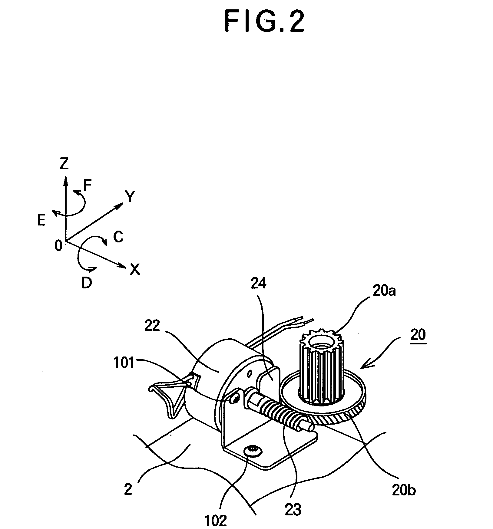
The disk-loading mechanism provides a rotation-transmitting mechanism for the loading motor without involving a friction type rotation-transmitting means, thereby allowing the rotational force of the loading motor to be transmitted reliably.

second embodiment

FIG. 8A is a perspective view of a mounting section of the loading motor according to a second embodiment.

The second embodiment differs from the first embodiment in that the loading motor 22 is mounted directly to a main chassis 12 without using a mounting member as a separate component. The rest of the construction is the same as that of the first embodiment.

FIG. 8B illustrates the loading motor as seen in the direction of the Y-axis from the origin.

Referring to FIGS. 8A and 8B, the main chassis 12 has a motor holder 12a formed in one piece therewith and the motor holder 12a holds the loading motor 22 in position. The motor holder 12a has a hole 12b formed therein and the loading motor 22 has a female-threaded hole 22a. The loading motor 22 is fixed to the motor holder 12a by screwing a bolt 101 into the female-threaded hole 22a through the hole 12b. The motor holder 12a is inclined so that the shaft 22b of the loading motor 22 makes an angle with the surface of the main chass...

third embodiment

FIG. 9 illustrates the shape of the worm 23 according to a third embodiment.

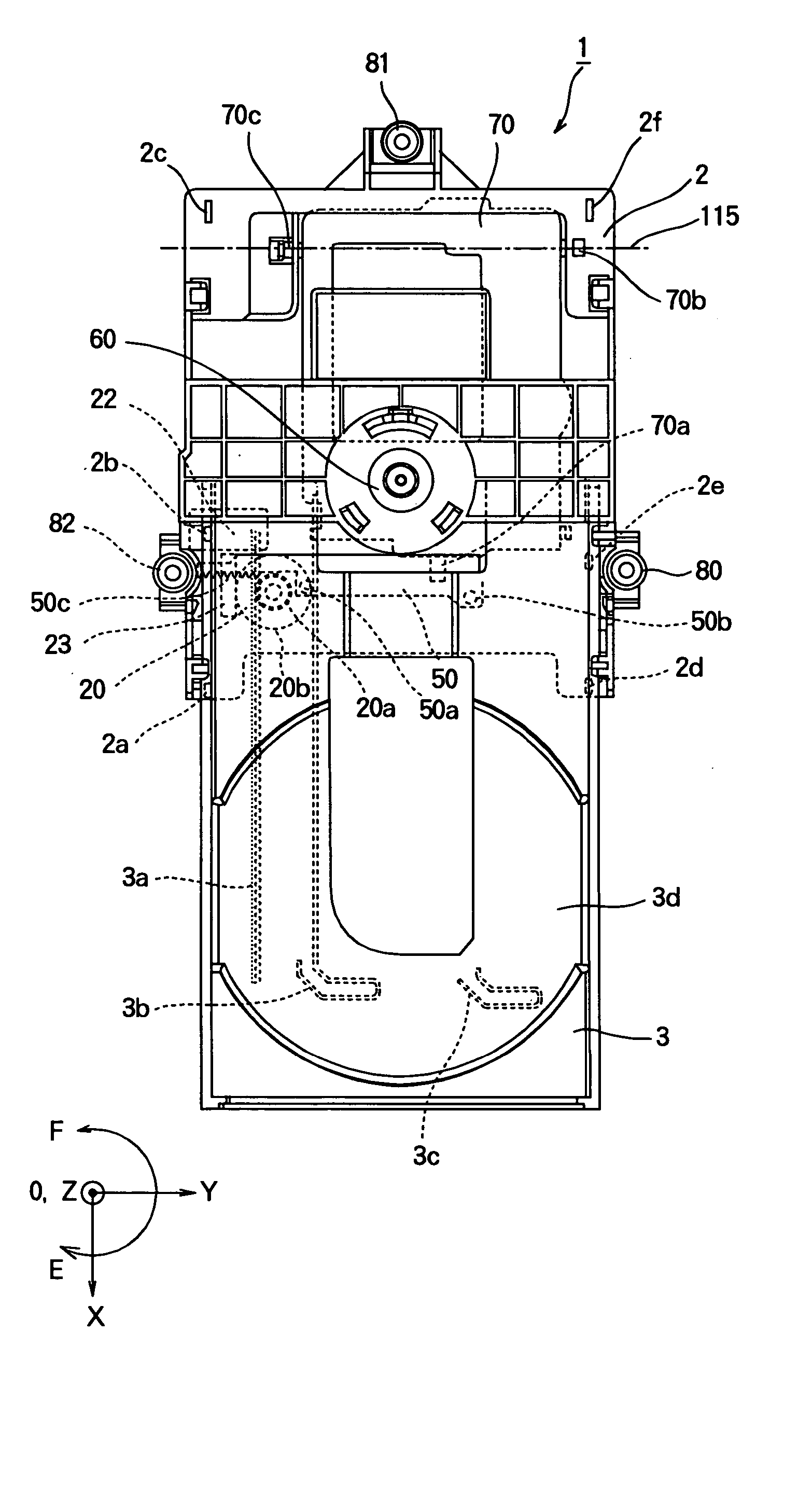
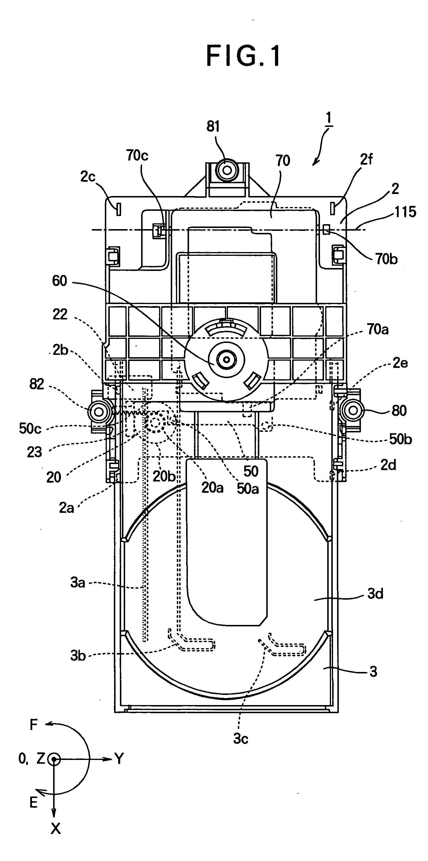
A disk loading apparatus is usually designed to perform an automatic pull-in function. That is, when a tray at the disk-discharging position is to be moved to the disk-loading position, a user directly pushes the tray into the apparatus and the movement of the tray or an urging force applied by the user to the tray is detected, and subsequently a loading motor is driven in rotation.

In order to perform the aforementioned automatic pull-in function, the disk-loading mechanism requires to be designed so that the tray moves in a direction in which the user pushes the tray. In other words, the apparatus should be designed such that the rotational force of the drive gear 20 that functions as a drive gear is smoothly transmitted to the worm 23 that functions as a driven gear.

The worm gear mechanism that includes the worm 23 and the worm wheel 20b can be self-locked when the worm wheel 20b functions as a drive...


PUM


Abstract

A main chassis supports a tray that carries a disk thereon and moves between a disk-discharging position and a disk-loading position. A motor is mounted on the main chassis and has a rotating shaft. A worm is formed on the rotating shaft. A drive gear rotatably is mounted on the main chassis and has a pinion gear and a worm wheel in mesh with the worm. The pinion gear is in mesh with a rack formed in the tray. The worm preferably satisfies a dimensional condition γo>Tan−1(μ/Cos αn) where γo is a lead, μ is friction coefficient, and an is normal pressure angle. The worm has a lead angle γo greater than 15°. The rotating shaft extends in a direction at an angle with a plane in which the drive gear rotates.

Description

BACKGROUND OF THE INVENTION 1. Field of the Invention The present invention relates to a disk-loading apparatus for loading a CD and a DVD to their reproducing positions, and more particularly to a rotation-transmitting mechanism that transmits the rotation of a loading motor. 2. Description of the Related Art FIG. 16 is a top view of a conventional disk-loading apparatus 100. Referring to FIG. 16, a main chassis 2 supports a tray 3 thereon such that guides 2a-2f guide the tray 3 to slide on the main chassis 2. The tray 3 carries a disk, not shown, placed thereon and moves into the apparatus for loading the disk and out of the apparatus for discharging the disk. The tray 3 is formed with a rack 3a in an underside thereof on one side of the tray 3. A drive gear 120 is rotatably mounted on the main chassis 2 and has a small gear 120a in mesh with the rack 3a. Likewise, a drive gear 121 is rotatably mounted on the main chassis 2 and has a small gear 121a in mesh with a large gear ...

Claims


Application Information

Patent Timeline
IPC IPC(8): G11B17/04
CPCG11B17/056
Inventor FUKASAWA, AKIHIRO
Owner MITSUBISHI ELECTRIC CORP
Why Eureka
Try Eureka