Connection system between a spinal rod and a transverse bar

a technology of connecting system and crossbar, applied in the field of osteosynthesis, can solve the problems of difficult control of clamping force, difficult installation and positioning of connectors on rods, and difficult operation of installing this system connecting crossbars and osteosynthesis rods

Inactive Publication Date: 2005-05-26
SCIENTX
View PDF24 Cites 130 Cited by
  • Summary
  • Abstract
  • Description
  • Claims
  • Application Information

AI Technical Summary

Problems solved by technology

However, it must be noted that the operation of installing this system connecting a crossbar and an osteosynthesis rod is very difficult to carry out properly.
However, the connector

Method used


Image

  • Connection system between a spinal rod and a transverse bar
  • Connection system between a spinal rod and a transverse bar
  • Connection system between a spinal rod and a transverse bar

Examples


Embodiment Construction

[0017] The present invention will now be described more fully hereinafter with reference to the accompanying drawings, in which preferred embodiments of the invention are shown. This invention may, however, be embodied in many different forms and should not be construed as limited to the embodiments set forth herein. Rather, these embodiments are provided so that this disclosure will be thorough and complete, and will fully convey the scope of the invention to those skilled in the art. Like numbers refer to like elements throughout, and prime notation is used to indicate similar elements in alternate embodiments.

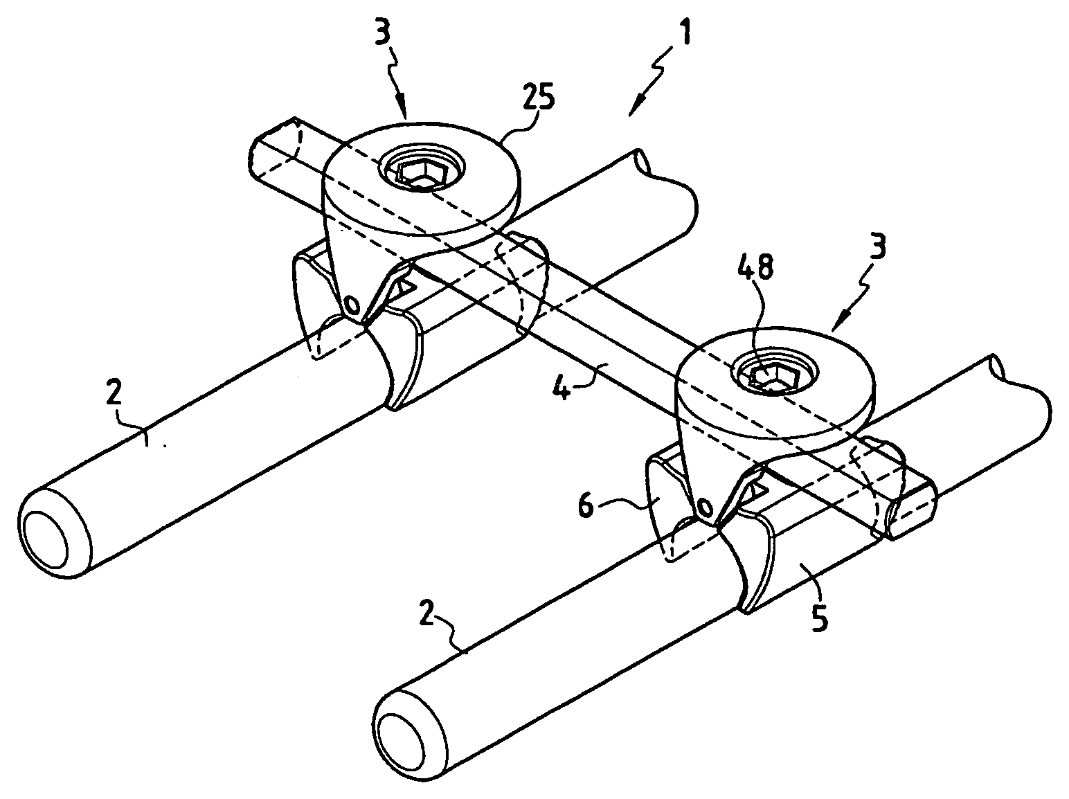
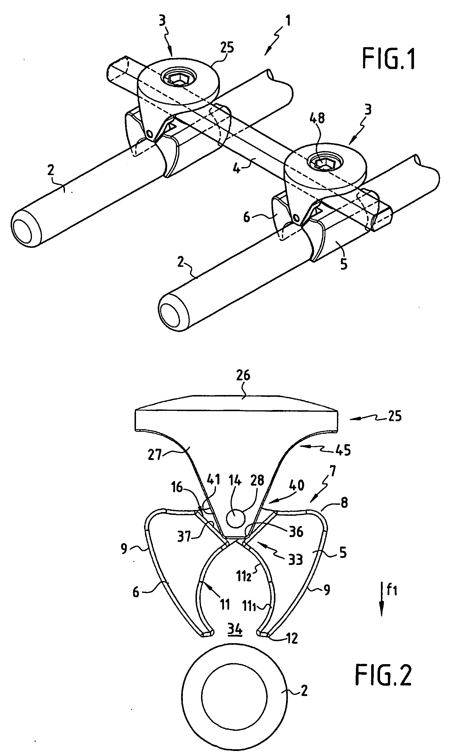
[0018] Referring initially to FIG. 1, FIG. 1 is a partial representation of an intervertebral connection device 1 including two spinal osteosynthesis rods 2 each of which has a circular cross-section and is designed to be fastened onto vertebrae by means of bone anchorage elements not shown but known in themselves, such as peduncular screws or hooks.

[0019] The purpose of t...


PUM


Abstract

A system for connecting a spinal osteosynthesis rod and a crossbar include a passage for receiving the corssbar and hinge mounted jaws for clamping the rod. A locking device biases the crossbar against the jaws. A return spring pulls the jaws relatively close to one another independently of the crossbar such that the jaws may clamp the osteosynthesis rod to ensure a stable mounting of the connection system to the osteosynthesis rod.

Description

CROSS-REFERENCE TO RELATED APPLICATIONS [0001] This application claims the benefit of International Application No. PCT / FR03 / 00425 filed Feb. 11, 2003, which claims priority to French Application No. 02 / 01626 filed Feb. 11, 2002 both of which are hereby incorporated herein in their entireties by reference.FIELD OF THE INVENTION [0002] This invention concerns the technical area of osteosynthesis in the general sense and covers, in particular, devices that permit an intervertebral connection capable of stabilizing the spine or correcting deformations of the spinal column. BACKGROUND OF THE INVENTION [0003] This invention more particularly covers the area of systems capable of providing a connection between a spinal osteosynthesis rod and a crossbar. [0004] In the state of the art, there are a number of known intervertebral connecting devices. In a conventional way, such a device includes bone anchoring elements such as, for example, peduncular implantation screws or vertebral hooks, e...

Claims


Application Information

Patent Timeline
IPC IPC(8): A61B17/58A61B17/70A61F2/44
CPCA61B17/7052
Inventor FRANCK, BRUNOMOKHTAR, MOURAD BENRYAN, DAVID
Owner SCIENTX
Why Eureka
Try Eureka