

Organic luminescence device with anti-reflection layer and organic luminescence device package
a luminescence device and anti-reflection layer technology, applied in the direction of discharge tube luminescnet screen, organic semiconductor device, discharge tube/lamp details, etc., can solve the problem of low efficiency of light emission to the exterior, and achieve satisfactory contrast and high light-emitting efficiency
- Summary
- Abstract
- Description
- Claims
- Application Information
AI Technical Summary
Benefits of technology
Problems solved by technology
Method used
Image

Examples
first embodiment
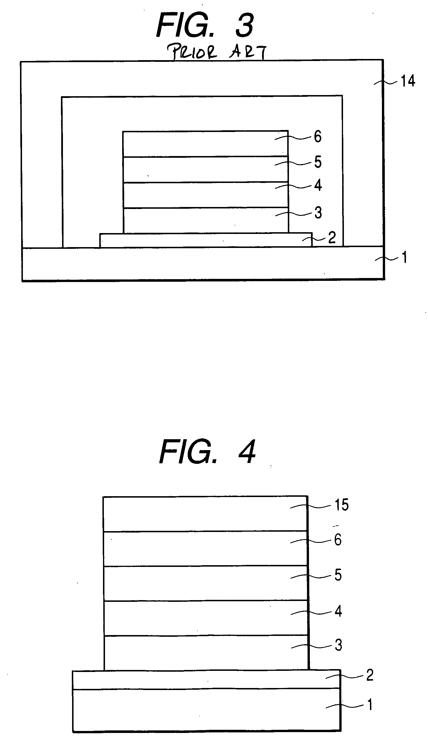
[0043] An organic luminescence device according to a first embodiment of the present invention is provided with an anti-reflection layer 15 on a transparent electrode 6 serving as a light-emitting electrode. Such anti-reflection layer may be of a single layer type or a multi layer type. FIG. 4 is a schematic cross-sectional view of an organic luminescence device of the first embodiment of the present invention, in which provided are a substrate 1, an electrode 2, a hole transporting layer 3, a light emitting layer 4, an electron injecting layer 5, a transparent electrode 6, and an anti-reflection layer 15 to constitute an organic luminescence device of so-called top emission type.
[0044] The anti-reflection layer prevents the reflection of the light emitted from the light emitting layer at the interface between the transparent electrode 6 and the external environment in which the organic luminescence device is present, thereby improving the light-emission efficiency of the device.
[...
second embodiment
[0048] An organic luminescence device according to a second embodiment of the present invention includes, in an organic luminescence device having a moisture preventing layer on the transparent electrode 6 serving as the light-emitting electrode, an anti-reflection layer on such moisture preventing layer. Other configurations are the same as those in the first embodiment. FIG. 5 is a schematic cross-sectional view of an organic luminescence device of the second embodiment of the present invention, in which provided are a substrate 1, an electrode 2, a hole transporting layer 3, a light emitting layer 4, an electron injecting layer 5, a transparent electrode 6, an anti-reflection layer 15, and a moisture preventing layer 16, to constitute an organic luminescence device of so-called top emission type.
[0049] The anti-reflection layer prevents the reflection of the light emitted from the light emitting layer at the interface between the moisture preventing layer 16 and the external env...
third embodiment
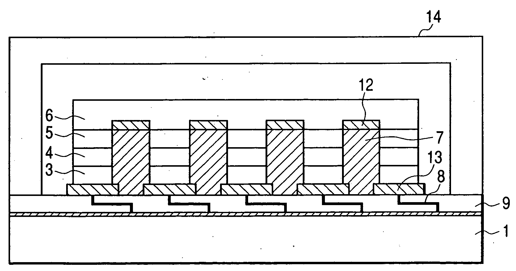
[0050] An organic luminescence device according to a third embodiment of the present invention utilizes, as an electrode provided at the substrate side, an electrode capable of preventing reflection of a light entering the device from the exterior, utilizing light absorption or by light interference. Other configurations are the same as those in the second embodiment. FIG. 6 is a schematic cross-sectional view of an organic luminescence device of the third embodiment of the present invention, in which provided are a substrate 1, an electrode 22 which intercepts the external light and prevents reflection thereof, a hole transporting layer 3, a light emitting layer 4, an electron injecting layer 5, a transparent electrode 6, an anti-reflection layer 15, and a moisture preventing layer 16, to constitute an organic luminescence device of so-called top emission type.
[0051] Thus, the organic luminescence device of the present embodiment is applicable also to an organic luminescence devic...
PUM
 Abstract
Description
Claims
Application Information