Lighting unit and projection display apparatus

a projection display and light source technology, applied in the direction of static indicating devices, instruments, optical radiation measurement, etc., can solve the problems of reducing the light emission efficiency of light emission

Inactive Publication Date: 2009-04-30
SANYO ELECTRIC CO LTD
View PDF6 Cites 22 Cited by
  • Summary
  • Abstract
  • Description
  • Claims
  • Application Information

AI Technical Summary

Benefits of technology

[0018]According to the above aspect, The lighting unit includes; a memory unit (correspondence relation memory unit 230) storing, for each of the plurality of state light sources, a correspondence relation between power supplied to each of the plurality of solid state light sources and the amount of light emitted from each of the plurality of solid state light sources, and an updating unit (degradation rate calculating unit 250) updating, for each of the plurality of state light sources, the correspondence relation in accordance with the amount of light emitted from the measurement target light source acquired by the acquisition unit. The light source controlling unit increases power supplied to a solid state light source having high light emission efficiency among the plurality of solid state light sources with reference to the memory unit, when increasing a total amount of light emitted from the plurality of solid state light sources.
[0019]According to the above aspect. The lighting unit includes; a memory unit (correspondence relation memory unit 230) storing, for each of the plurality of state light sources, a correspondence relation between power supplied to each of the plurality of solid state light sources and the amount of light emitted from each of the plurality of solid state light sources, and an updating unit (degradation rate calculating unit 250) updating, for each of the plurality of state light sources, the correspondence relation in accordance with the amount of light emitted from the measurement target light source acquired by the acquisition unit The light source controlling unit reduces power supplied to a solid state light source having low light emission efficiency among the plurality of solid state light sources with reference to the memory unit, when reducing the total amount of light emitted from the plurality of solid state light sources.

Problems solved by technology

However, only a single solid state light source does not secure a required amount of light for a projection display apparatus.
Meanwhile, solid state light sources are degraded in some cases due to change of ambient temperature of the solid state light sources.
Additionally, solid state light sources also degrade with time in some cases.
Accordingly, the number of sensors increases as the number of light sources increases, so that the production cost of a projection display apparatus increases.
In addition, as the number of sensors increases, the control on each sensor becomes more complicated.
In addition, the provision of a plurality of solid state light sources to the projection display apparatus causes the following problem.
Specifically, even when a plurality of sensors corresponding respectively to the plurality of solid state light sources are provided, the exact detection of only the light emitted from each of the solid state light sources is difficult.

Method used


Image

  • Lighting unit and projection display apparatus
  • Lighting unit and projection display apparatus
  • Lighting unit and projection display apparatus

Examples


first embodiment

(Configuration of a Projection Display Apparatus)

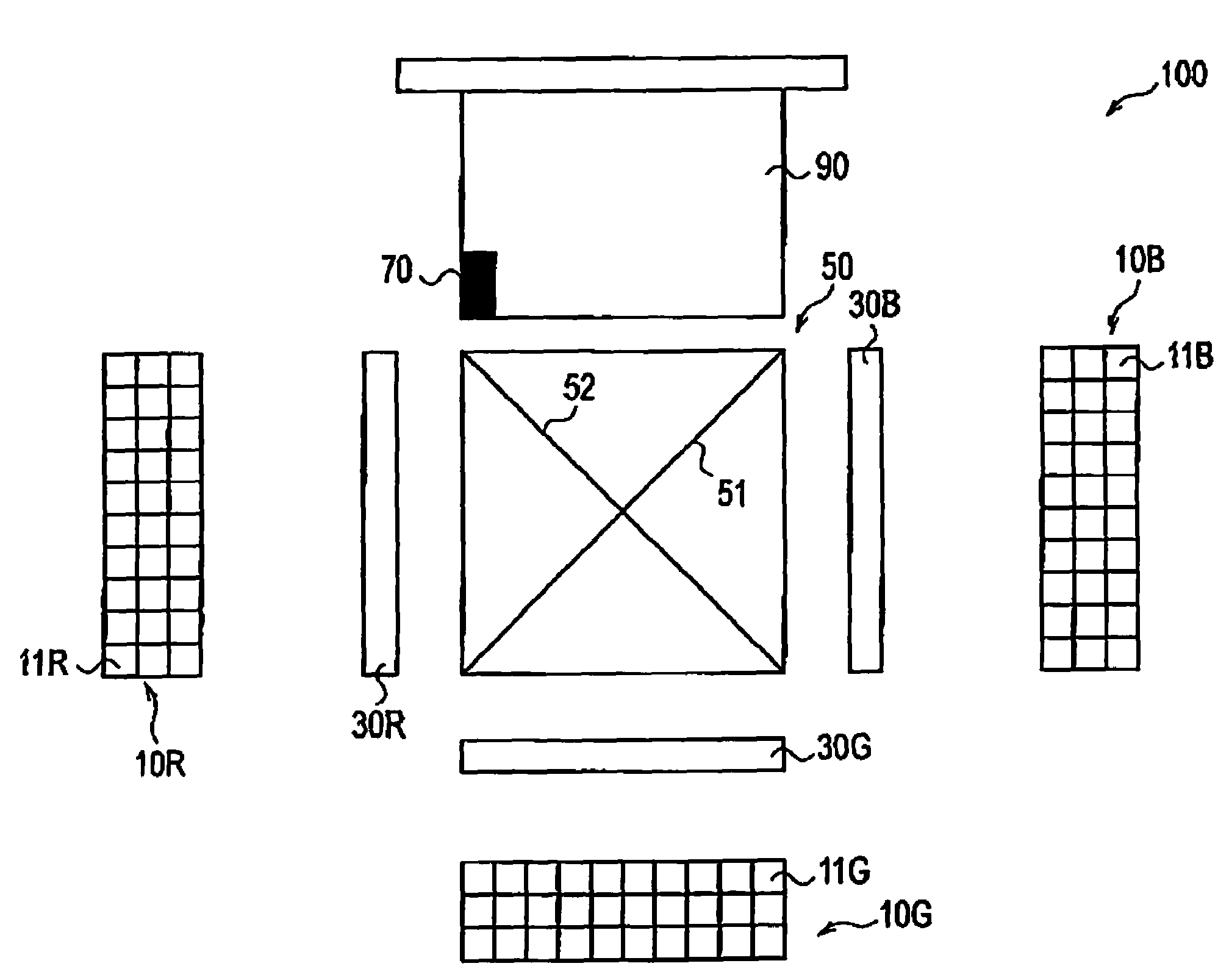
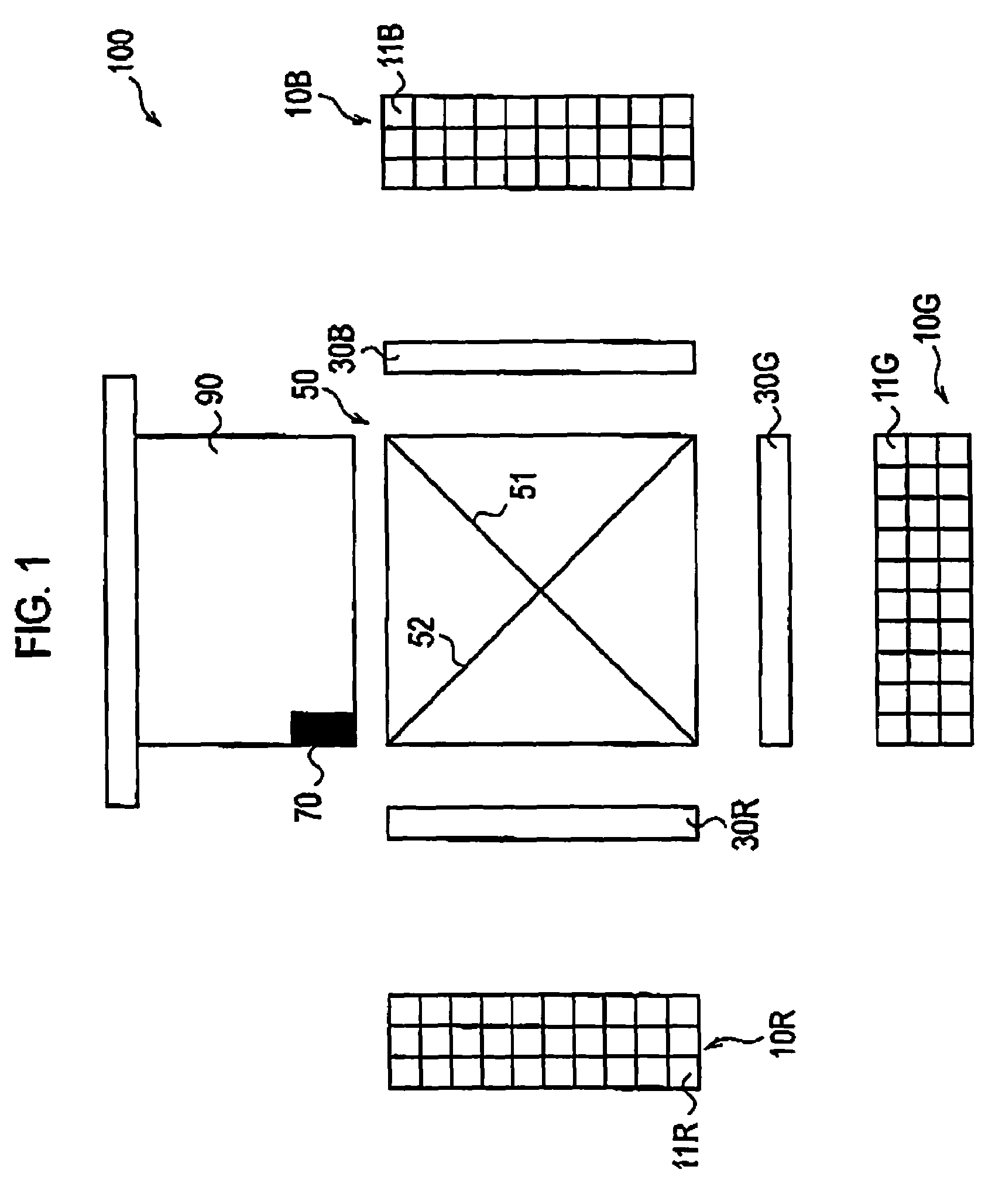
[0042]The configuration of a projection display apparatus according to a first embodiment of the present invention is described below with reference to drawings. FIG. 1 is a schematic view showing a configuration of a projection display apparatus 100 according to the first embodiment

[0043]As shown in FIG. 1, the projection display apparatus 100 includes a plurality of array light sources 10 (array light sources 10R, 10G and 10B) in which a plurality of solid state light sources 11 (solid state light sources 11R, 11G, and 11B) are arranged in array; a plurality of light imagers 30 (light imagers 30R, 30G, and 30B); a cross dichroio prism 50; and a projection lens unit 90 provided with a light amount sensor 70.

[0044]It should be noted that in FIG. 1, an optical element (e.g., a tapered rod or a fly eye lens) for uniformizing light emitted from the array light sources 10, and the like are omitted for a clear description.

[0045]The array l...

modification 1

(Modification 1)

[0121]In Modification 1, as in the light source control example 7, timing at which only a measurement target light source corresponding to any one of the plurality of solid state light sources 11a is set to a non-emission state is provided. The light source controlling unit 240 controls a ratio (duty) in one frame section (a predetermined period).

[0122]However. In the modification 1, when a bright image (white 100% image) is displayed, assumption is made on a case where all the plurality of solid state light sources 11a must emit light.

[0123]In the light source control example 7, a measurement of the amount of light is made when the amount of spare light is not less than a resultant amount of light after the reduction by the measurement target light source. In Modification 1, a difference between an amount of light when all the plurality of solid state light sources 11a emit light, and an amount of light being calculated, by the light source controlling unit 240, as ...

modification 2

(Modification 2)

[0153]In Modification 2, a temperature sensor 71 is provided to measure the array light sources 10, and a detection result by the light amount sensor 70 is corrected on the basis of a measurement result by the temperature sensor 71.

[0154]FIG. 13 is a block diagram showing a configuration of Modification 2. Provided is a temperature sensor 71 for measuring the temperature of the array light sources 10 which transfers the measurement result to the degradation rate calculating unit 250.

[0155]The degradation rate calculating unit 250 makes a temperature correction to the measurement result by the light amount sensor 70 on the basis of data from the temperature sensor 71.

[0156]A specific temperature correction method is described with reference to FIG. 14. Firstly, the temperature sensor 71 previously acquires temperature characteristics (power versus temperature dependency of an amount of light) on all the plurality of solid state light sources 11a, and stores the charac...


PUM


Abstract

A projection display apparatus 100 including a plurality of solid state light sources 11 includes: a sensor 70 detecting an amount of light emitted from the plurality of solid state light sources 11; a degradation rate calculating unit 250 acquiring, from the amount of light detected by the sensor 70, an amount of light emitted from a measurement target light source which is any one of the plurality of solid state light sources: and a light source controlling unit 240 controlling, for each of the plurality of state light sources 11, emission periods in which the plurality of solid state light sources 11 emit light so that the degradation rate calculating unit 250 acquires the amount of light emitted from the measurement target light

Description

BACKGROUND OF THE INVENTION[0001]1. Field of the Invention[0002]The present invention relates to a lighting unit provided with a plurality of solid state light sources, and a projection display apparatus.[0003]2. Description of the Related Art[0004]A projection display apparatus has heretofore been known, which is provided with a light imager (a liquid crystal panel or the like) for modulating light emitted from a light source. The projection display apparatus projects, on a screen, the light modulated by the light imager. In addition, an attempt has been made to employ a solid state light source such as a laser diode or an LED, for a light source provided to a projection display apparatus.[0005]However, only a single solid state light source does not secure a required amount of light for a projection display apparatus. Therefore, a plurality of solid state light sources have generally been provided to a projection display apparatus.[0006]Meanwhile, solid state light sources are deg...

Claims


Application Information

Patent Timeline
Patent Type & Authority Applications(United States)
IPC IPC(8): G03B21/20G01J1/32
CPCG01J1/32G09G3/001H05B33/0869G03B21/2033G03B21/2053G03B21/2013H05B33/0893H05B45/22H05B45/58
Inventor HARAGUCHI, MASAHIROTANASE, SUSUMUHIRANUMA, YOSHINAOTERAUCHI, TOMOYAABE, TAKAAKIINOUE, MASUTAKA
Owner SANYO ELECTRIC CO LTD
Why Eureka
Try Eureka