
Portable cooler with built-in refrigerant cubes
a cooler and refrigerant technology, applied in the field of portable coolers, can solve the problems of occupying a lot of otherwise usable space, inconvenient handling and positioning of containers and packets of freezable materials, and inconvenient storage, so as to achieve convenient storage and little space
- Summary
- Abstract
- Description
- Claims
- Application Information
AI Technical Summary
Benefits of technology
Problems solved by technology
Method used
Image

Examples
Embodiment Construction
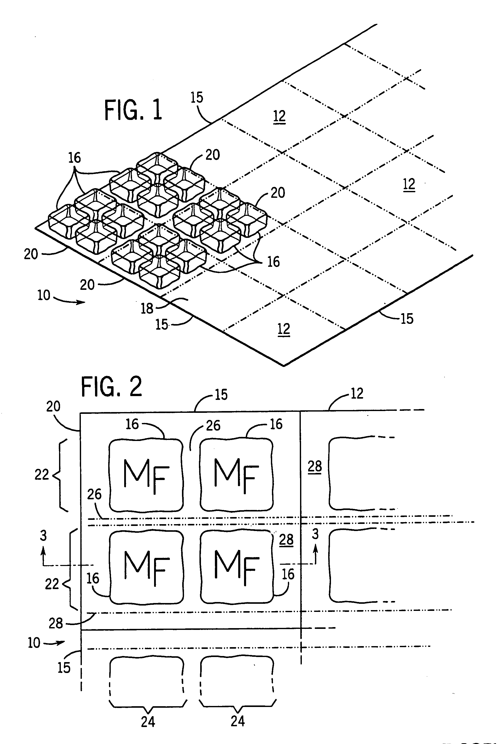
[0040] Referring now to FIGS. 1 and 2, an ice sheet 10 is shown including a flexible but generally planar backing layer 12 and including a large number of spaced apart refrigerant cubes 16 disposed along its upper surface 18. The refrigerant cubes 16 are preferably grouped in sections 20 each of which have four cubes. The refrigerant cubes are deployed in rows 22 and columns 24 separated by lanes 26 and 28 running across the sheet 10 from its perimeter edges 15. The sectional lanes 28 running between the sections 20 of refrigerant cubes 16 are preferably somewhat wider than the other lanes between the cubes. The refrigerant cubes 16 in FIG. 2 are each shown as having a logo (the letters MF) stamped or embossed on their top surfaces.
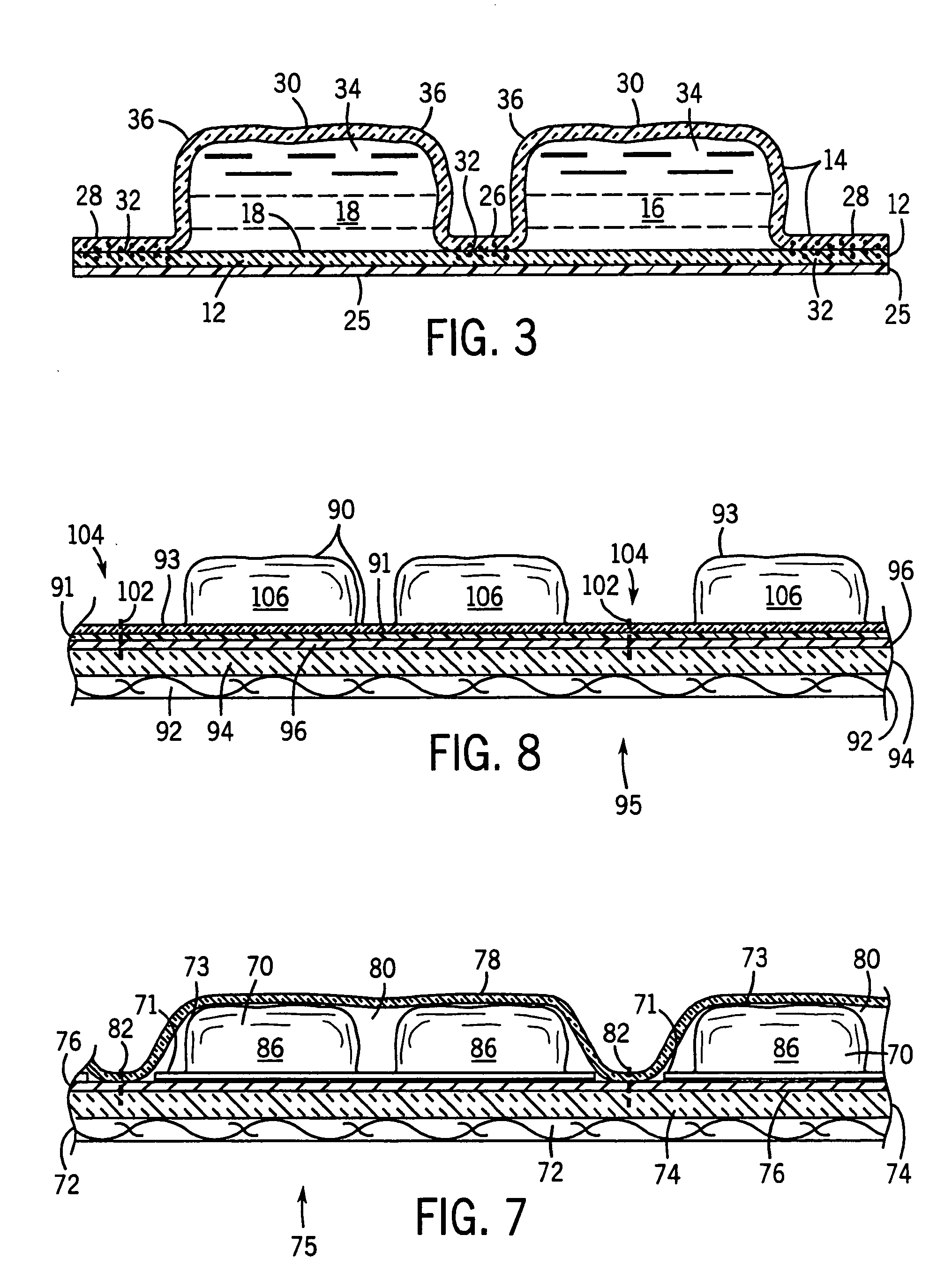
[0041] Referring now to FIG. 3, a top layer 14 is formed into cup-shaped sections 30 and heated-sealed at joints 32 along the lanes 26 and 28 to the upper surface 18 of backing layer 12 so as to form small ice cube-like sealed compartments 34 in which th...
PUM
 Abstract
Description
Claims
Application Information