Light adjuster and laminated glass

a technology of light adjuster and laminated glass, which is applied in the direction of instruments, non-linear optics, coatings, etc., can solve the problems of ec device not being able to be used as a light adjuster, and affecting the effect of light adjustment speed

Inactive Publication Date: 2005-09-01
NIPPON SHEET GLASS CO LTD
View PDF4 Cites 17 Cited by
  • Summary
  • Abstract
  • Description
  • Claims
  • Application Information

AI Technical Summary

Benefits of technology

[0014] To attain the above object, in a second aspect of the present invention, there is provided a light laminated glass including a pair of glass sheets facing each other, intermediate layers provided on respective facing surfaces of the pair of glass sheets, and a light adjuster sandwiched between the intermediate layers, characterized in that the light adjuster comprises a liquid crystal layer having a plurality of voids therein, each of the voids being filled with a liquid crystal material, a pair of substrates that sandwich the liquid crystal layer therebetween, at least one of the substrates being transparent, transparent electrically conductive films provided on respective facing surfaces of the substrates, to which power is su

Problems solved by technology

However, because such an EC device is current driven, if the EC device is made to have a large area, then a large voltage drop arises, the response speed drops markedly, and degradation of constituent materials due to electrochemical chan

Method used


Image

  • Light adjuster and laminated glass
  • Light adjuster and laminated glass
  • Light adjuster and laminated glass

Examples


first embodiment

[0019] A light adjuster according to the present invention will now be described with reference to the drawings.

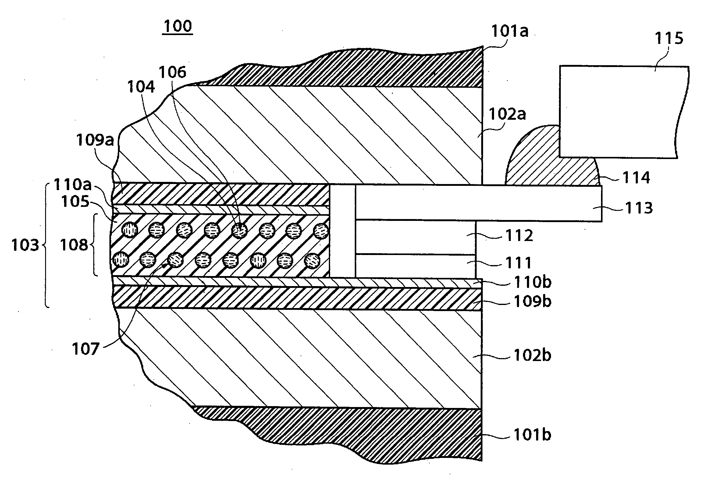
[0020]FIG. 1 is a sectional view of the schematic construction of a laminated glass using the light adjuster according to the first embodiment of the present invention.

[0021] In FIG. 1, the laminated glass 100 is comprised of a pair of glass sheets 101a and 101b that are disposed in facing relation to each other, transparent intermediate layers 102a and 102b provided on respective facing surfaces of the glass sheets 101a and 101b that are formed of, for example, EVA (copolymer of ethylene vinyl acetate), and a light adjuster 103, described below, that is sandwiched between the intermediate layers 102a and 102b.

[0022] The light adjuster 103 is comprised of a liquid crystal layer 108 formed of a transparent polymer film 105 made of a latex having a plurality of voids 104 therein, and liquid crystal capsules 107 formed of liquid crystal molecules 106 being filled in the voi...

second embodiment

[0030] Next, a description will be given of a light adjuster according to the present invention with reference to the drawings.

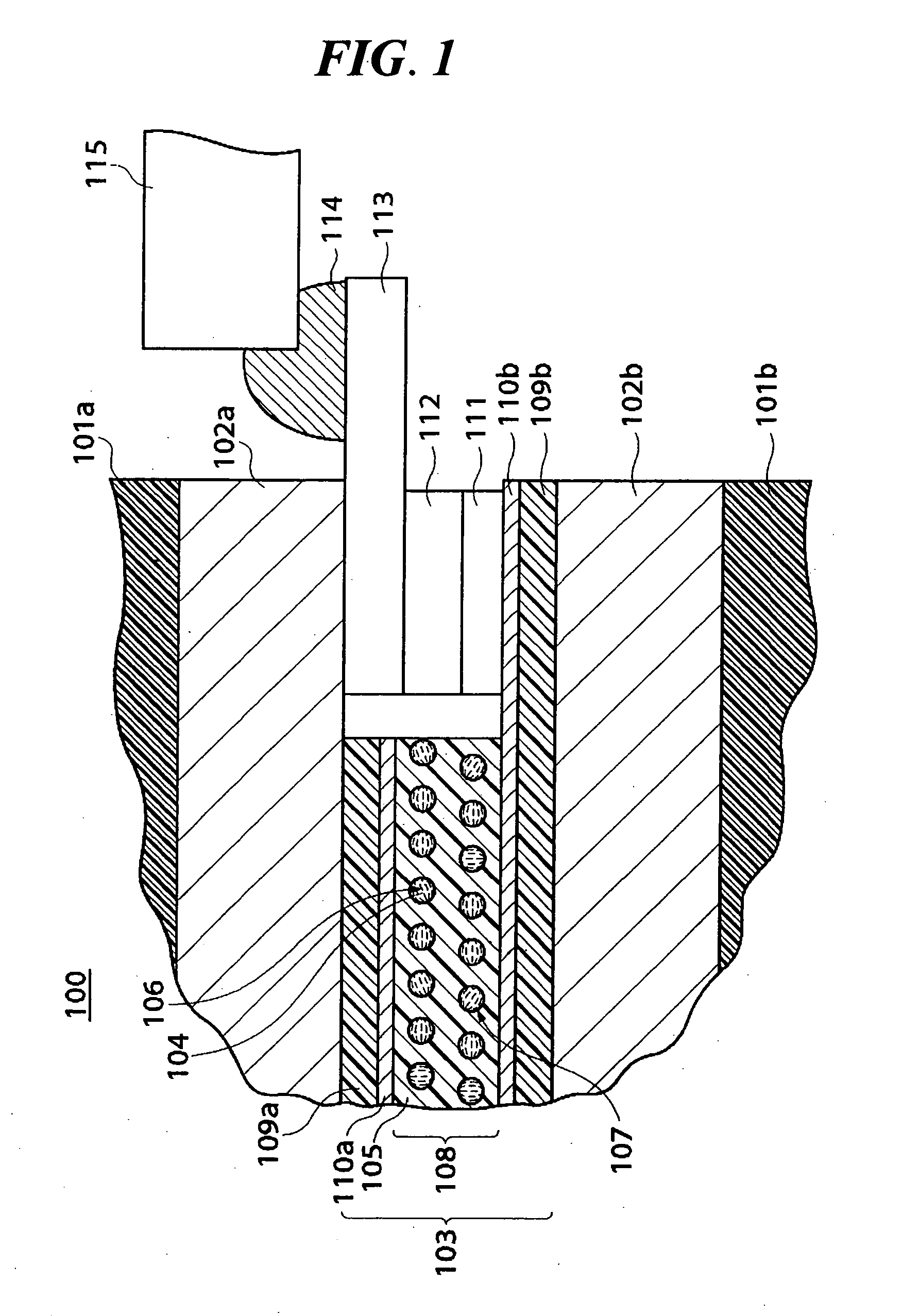
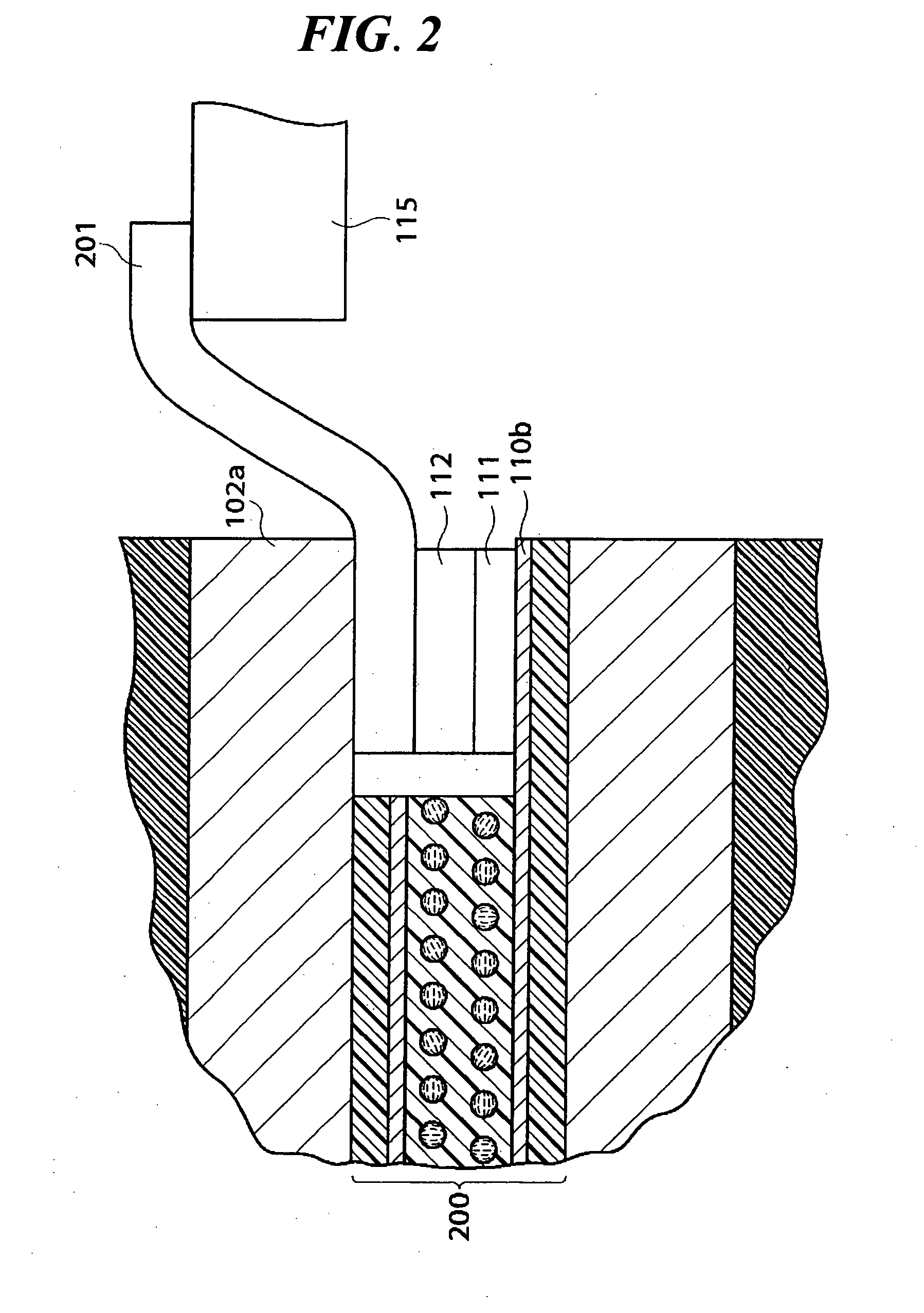
[0031]FIG. 2 is a sectional view of the schematic construction of a laminated glass using the light adjuster according to the second embodiment of the present invention.

[0032] In the second embodiment, the construction and operation are basically the same as those of the first embodiment described above and thus description of parts of the construction and operation which are redundant is omitted, and a description will be given of parts of the construction and operation which differ from the first embodiment.

[0033] In FIG. 2, the light adjuster 200 includes an electrode structure comprised of a connecting base formed of the silver paste 111 that is applied to an exposed part of the transparent electrically conductive film 110b at one end of the light adjuster 200, and the copper tape 112 that is stuck on the upper surface of the silver paste 111, and a co...


PUM

PropertyMeasurementUnit
Thicknessaaaaaaaaaa
Electrical conductivityaaaaaaaaaa
Poweraaaaaaaaaa

Abstract

There is provided a light adjuster which is capable of improving handleability thereof and preventing the occurrence of operation failure. A light adjuster 103 is comprised of a pair of PET films 109a and 109b that sandwich a liquid crystal layer 108 therebetween, transparent electrically conductive films 110a and 110b that are provided on respective facing surfaces of the pair of PET films 109a and 109b, and an electrode structure provided at one end of the light adjuster 103. The electrode structure is comprised of a connecting base formed of a silver paste 111 that is applied to an exposed part of the transparent electrically conductive film 110b, a copper tape 112 that is stuck on the upper surface of the silver paste 111, and a tabular connector 113 made of a metal that is pressed onto the copper tape 112 at one end thereof. A lead line 115 is secured to the other end of the connector 113 by solder 114 to supply power from an external power source. The thickness of the electrode structure is not less than the value of the combined thickness of the liquid crystal layer 108, the transparent electrically conductive film 110a, and the PET film 109a.

Description

TECHNICAL FIELD [0001] The present invention relates to a light adjuster and a laminated glass having a liquid crystal material therein, and in particular relates to a light adjuster and a laminated glass that enables visual field control. BACKGROUND ART [0002] Hitherto, electrochromic devices (hereinafter referred to as “EC devices”) have been known as devices such as light adjusters having a light adjusting capability of enabling the transmissivity to be freely adjusted (hereinafter referred to as “light adjusting devices”). Such an EC device is, for example, made from a material that undergoes a spectral change upon an electrochemical redox reaction, such as tungsten oxide or prussian blue, and controls the transmitted light by absorbing light. However, because such an EC device is current driven, if the EC device is made to have a large area, then a large voltage drop arises, the response speed drops markedly, and degradation of constituent materials due to electrochemical chang...

Claims


Application Information

Patent Timeline
IPC IPC(8): B32B17/10E06B9/24C03C27/12G02F1/13G02F1/1333G02F1/1334G02F1/1345
CPCB32B17/10B32B17/10036B32B17/10174G02F1/1334G02F2201/503G02F1/13452B32B2367/00B32B17/10005G02F1/1345C03C27/10
Inventor YANO, YUICHI
Owner NIPPON SHEET GLASS CO LTD
Why Eureka
Try Eureka