
Eureka
For R&D, Eureka makes reading and utilizing patents & technical documents easy.
Eureka AIR
Designed for self-driven R&D workflows. Generate viable solutions, solve complex R&D challenges, empower your innovation with AI.

Eureka Materials
Designed for material experts only. Revolutionize your material R&D, from search, analyze, to developing new materials.

TechResearch
Generate reliable direction feasibility study reports for your R&D in just a few steps.

TechSeek
Discover and master advanced knowledge NOW. Basics, ideas, possibilities, all at once.

TechMind
As an expert in R&D Theories, TechMind can generates customized viable solutions instantly.

TechRisk
Analyze your overall solution with one click, know your potential R&D risks in advance.

TechMonitor
Get weekly tech updates, stay abreast of the latest tech innovations and key insights.
Rack for holding objects on
- Summary
- Abstract
- Description
- Claims
- Application Information
AI Technical Summary
Benefits of technology
Problems solved by technology
Method used
Image

Examples
Embodiment Construction
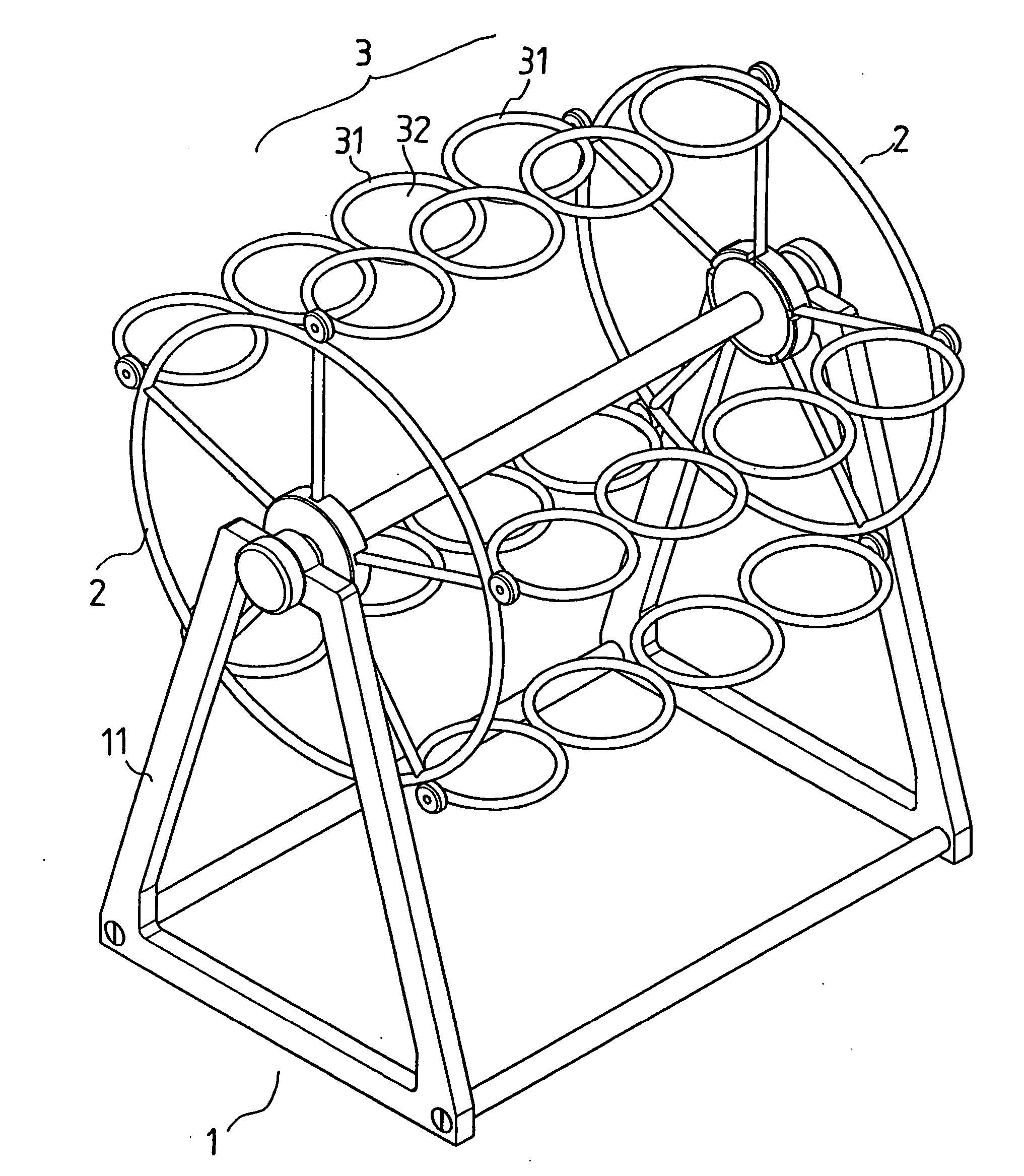
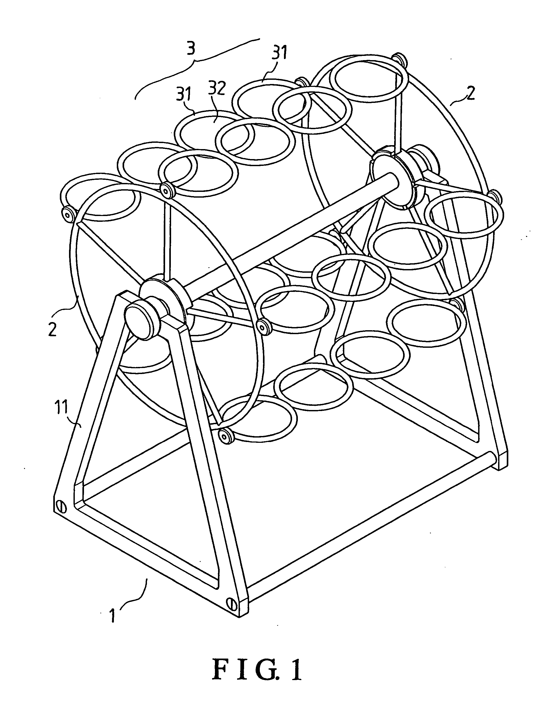
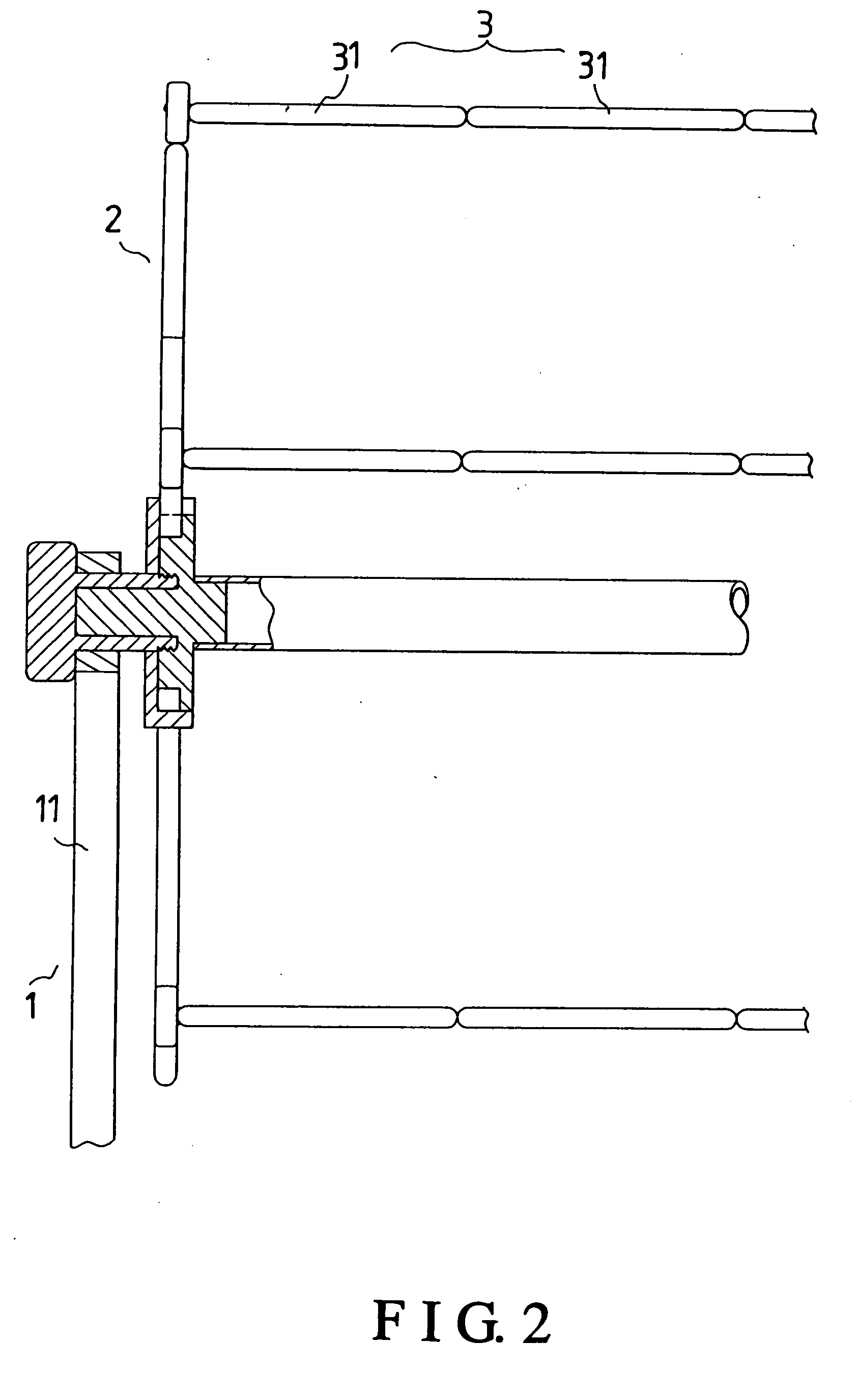
[0013] Referring to FIGS. 1 to 3, a preferred embodiment of the rack of the present invention includes a main frame 1, two rotary frames 2, and several holding rack parts 3.
[0014] The main frame 1 has two lateral supporting portions 11 at two ends, which are projected upwards, and opposed with each other. The rotary frames 2 are pivoted to respective ones of the lateral supporting portions 11 of the main frame 1. The holding rack parts 3 are each pivoted to the rotary frames 2 at two ends thereof. And, each of the holding rack parts 3 has several rings 31 connected together for holding objects, e.g. bottles, cups, and jars, in position, each of which rings 31 has a receiving hole 32 for allowing objects to be passed through. The rings 31 are formed with different diameters for suiting various objects.
[0015] Referring to FIGS. 1 and 4, to hold objects such as bottles, cups, and jars on the present rack, the objects are passed through, and kept in position by the rings 31 of the hol...
PUM
 Abstract
Description
Claims
Application Information
 - R&D Engineer
- R&D Manager
- IP Professional
- Industry Leading Data Capabilities
- Powerful AI technology
- Patent DNA Extraction
Browse by: Latest US Patents, China's latest patents, Technical Efficacy Thesaurus, Application Domain, Technology Topic, Popular Technical Reports.
© 2024 PatSnap. All rights reserved.Legal|Privacy policy|Modern Slavery Act Transparency Statement|Sitemap|About US| Contact US: help@patsnap.com