Protection method and system for equipment in a network element

a network element and equipment technology, applied in the field of telecommunications networks, can solve the problems of not being able to completely protect, 1+1 protection, and multiple concurrent failures, and achieve the effect of reducing or eliminating elements problems and disadvantages

Inactive Publication Date: 2005-09-08
FUJITSU LTD
View PDF8 Cites 7 Cited by
  • Summary
  • Abstract
  • Description
  • Claims
  • Application Information

AI Technical Summary

Benefits of technology

[0005] The present invention provides a protection method and system for equipment in a network element of a telecommunications network that significantly reduce or eliminate elements problems and disadvantages associated with previous systems and methods. In particular, the present invention prioritizes protection for failed equipment based on both protection request type and failed equipment type.
[0008] Technical advantages of the present invention include providing an improved method and system for protecting equipment in a network element. In a particular embodiment, a plurality of equipment items are protected by a single item with protection priority being provided based on protection request type and failed equipment type. Accordingly, during multiple concurrent failures of equipment, the most important equipment item at the highest protection request level is protected. This improves network performance and provides for a more deterministic network that can be more fully controlled by network operators.
[0009] Another technical advantage of one or more embodiments of the present invention includes providing greater protection switching granularity. In particular, protection switching is provided for DS-1 and / or other cards supporting single connections on an 1:N basis. Thus, low level elements may be partially protected in a network element while higher level elements are fully protected. This allows the majority of traffic to be fully protected while limited protection is provided for individual flows on an efficient basis.

Problems solved by technology

This 1+1 protection, however, is expensive to maintain as fully half of the networks capacity is maintained in reserved for protection switching and is not used during normal operation of the network.
Multiple concurrent failures, however, cannot be completely protected.
Within the priorities, equipment is protected on a first failed basis, which can lead to less important equipment being protected at the expense of later failing, more important equipment.

Method used


Image

  • Protection method and system for equipment in a network element
  • Protection method and system for equipment in a network element
  • Protection method and system for equipment in a network element

Examples


Embodiment Construction

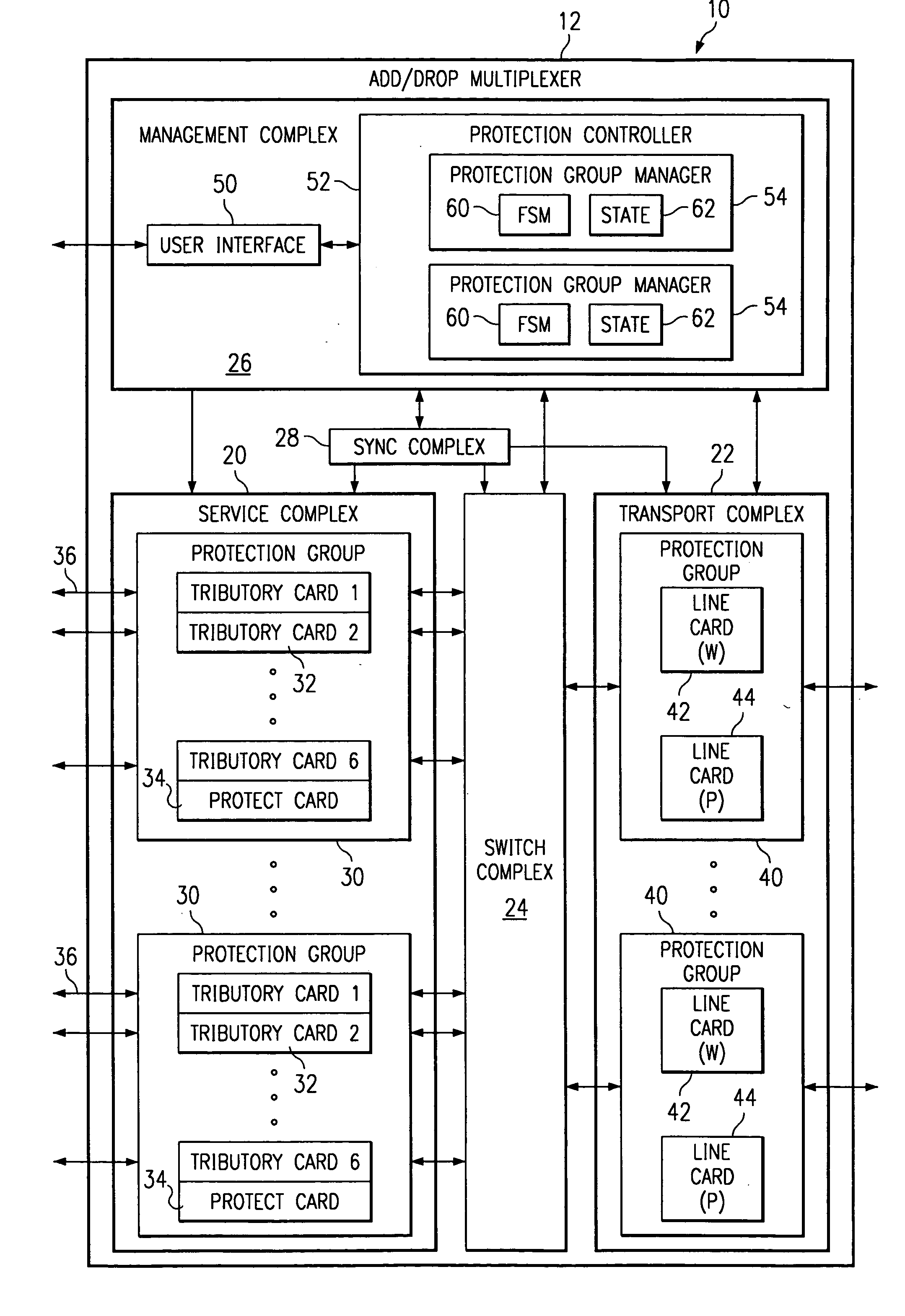
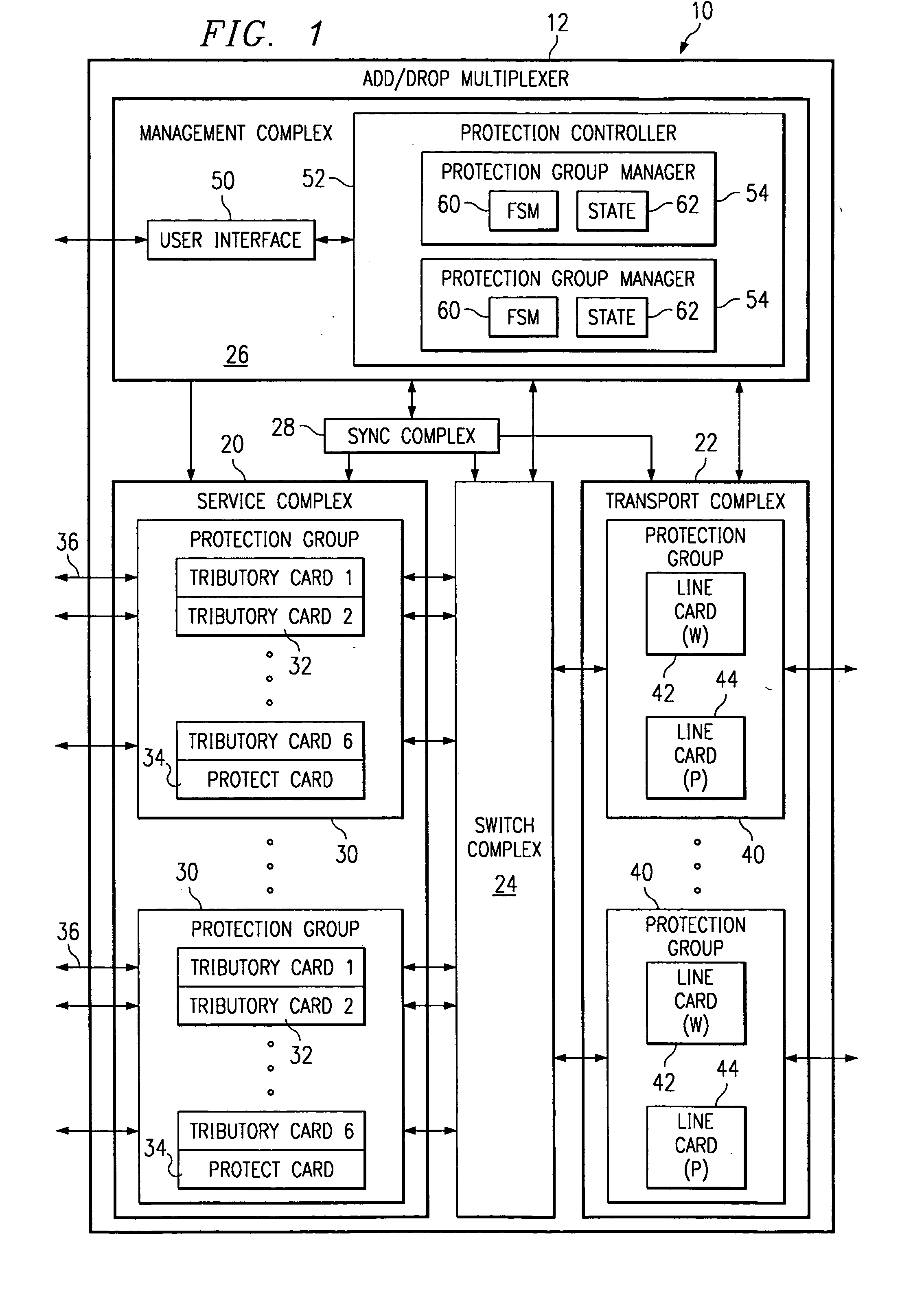
[0018]FIG. 1 illustrates a network element 10 for a telecommunications network in accordance with one embodiment of the present invention. The telecommunications network transmits voice, data, or other suitable types of information, and / or a combination of types of information between end users. The telecommunications network may include a public network such as the Internet and the public switched telephone network (PSTN) as well as private networks such as wide area networks (WAN) and local area networks (LAN).

[0019] The telecommunications network includes a plurality of network elements interconnected by transmission links. The network elements may comprise a switch, router, add / drop multiplexer, access device or other suitable device capable of directing traffic in the telecommunications network. The transmission links provide the physical interface between the network elements. The physical interfaces are defined by bandwidth of the connecting transmission links which may be D...


PUM


Abstract

A protection method and system for equipment in a network element receives a protection request for an equipment item. A priority of the request and a priority of the equipment item is evaluated relative to all other outstanding protection requests for equipment items in a protection group with the equipment item. A highest priority protection request for a highest priority equipment item is performed.

Description

TECHNICAL FIELD OF THE INVENTION [0001] This invention relates generally to the field of telecommunications networks, and more particularly, to a protection method and system for equipment in a network element. BACKGROUND OF THE INVENTION [0002] Telecommunications networks transmit voice and other data between end users. The networks include switch and management nodes for processing and routing traffic in the network and links between the nodes for carrying the traffic. The links are circuit switched or packet switched wireline links, wireless links, or a combination of link types. End users communicate data over telephones, computers, personal digital assistants (PDA) and other similar devices. [0003] Telecommunication nodes include redundant equipment and are connected to redundant to provide fault tolerance and allow continued operation in the event of equipment or link failure. Typically, each transmission link as well as line or switch cards of the nodes are backed up by corre...

Claims


Application Information

Patent Timeline
Patent Type & Authority Applications(United States)
IPC IPC(8): G01R31/08H04J3/14H04L12/26
CPCH04J3/14
Inventor RAJAN, RAGHUDHARAMRAJ, DANNY
Owner FUJITSU LTD
Why Eureka
Try Eureka