
Metal frame and glass pane door element, window element, systems including same, and method for making same

a metal frame and glass pane technology, applied in the field of door systems, window systems, and methods for making door systems and window systems, can solve the problems of requiring expensive repairs or replacements by building owners, affecting the appearance of the building, so as to improve the appearance, improve the construction, and improve the effect of product quality and performan

Active Publication Date: 2020-02-04
PORTELLA IND LLC
View PDF16 Cites 6 Cited by
  • Summary
  • Abstract
  • Description
  • Claims
  • Application Information

AI Technical Summary

Benefits of technology

This patent is about a door system with a metal frame and window pane that have improved construction and appearance. This system has high product quality and performance, reduces delamination failures, and simplifies manufacturing steps, consistency of product quality, and reduces waste and cost. Additionally, the patent also improves the method of manufacturing and product quality by reducing impact of environmental variations and simplifying manufacturing and installation.

Problems solved by technology

Such metal frame and glass pane elements may be constructed by cold-forming metals to form the frame profiles, and thus may be difficult and time-consuming to manufacture.
Elements having sandwich constructions may suffer delamination failures, requiring expensive repairs or replacement by building owners or the manufacturer.
Determining and addressing root causes of delamination failures may require major investigation, engineering analysis, changes in product designs and manufacturing methods, and also may require long periods of testing.
Undesired or unacceptable variations in product quality may be caused, over long periods of production.

Method used


Image

  • Metal frame and glass pane door element, window element, systems including same, and method for making same
  • Metal frame and glass pane door element, window element, systems including same, and method for making same
  • Metal frame and glass pane door element, window element, systems including same, and method for making same

Examples


Embodiment Construction

[0026]In the following detailed description, reference is made to the accompanying drawings which form a part hereof, and in which is shown by way of illustration specific embodiments which may be practiced. These embodiments are described in sufficient detail to enable those skilled in the art to practice the embodiments and disclosure. It is to be understood that other embodiments may be utilized, and that logical, mechanical, electrical, and other changes may be made without departing from the scope of the embodiments and disclosure. In view of the foregoing, the following detailed description is not to be taken as limiting the scope of the embodiments or disclosure.

[0027]The terminology used herein is for the purpose of describing particular embodiments only and is not intended to be limiting. As used herein, the singular forms “a”, “an”, and “the” are intended to include the plural forms as well, unless the context clearly indicates otherwise. It will be further understood that...


PUM


Abstract

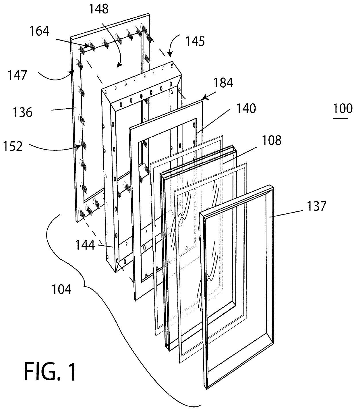
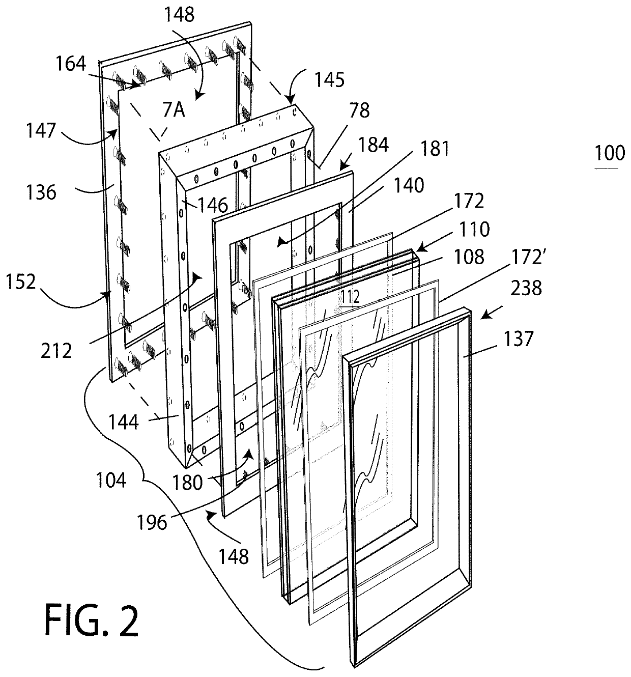
An element, having an insulating glass unit mounted in a metal frame assembly, may include an outer frame assembly comprising a unitary outer frame member, a plurality of mounting studs projecting from said outer frame member in perpendicular relationship in a first pattern aligned with a first complementary pattern of mounting bores defined in an insulation body assembly when the outer frame member is disposed in common alignment with the insulation body assembly, an inner frame assembly including a multi-part inner frame member having a set of discrete inner frame side members, a plurality of mounting studs projecting from the inner frame member in a second pattern aligned with a second complementary pattern of mounting bores in a rear surface of the insulation body assembly, each mounting bore having a respective mounting bore sidewall spaced from an aligned mounting stud received therein, and a curing connection medium in the plurality of mounting bores to define a plurality of mounting connections from the inner and outer frame assemblies to the insulating body assembly.

Description

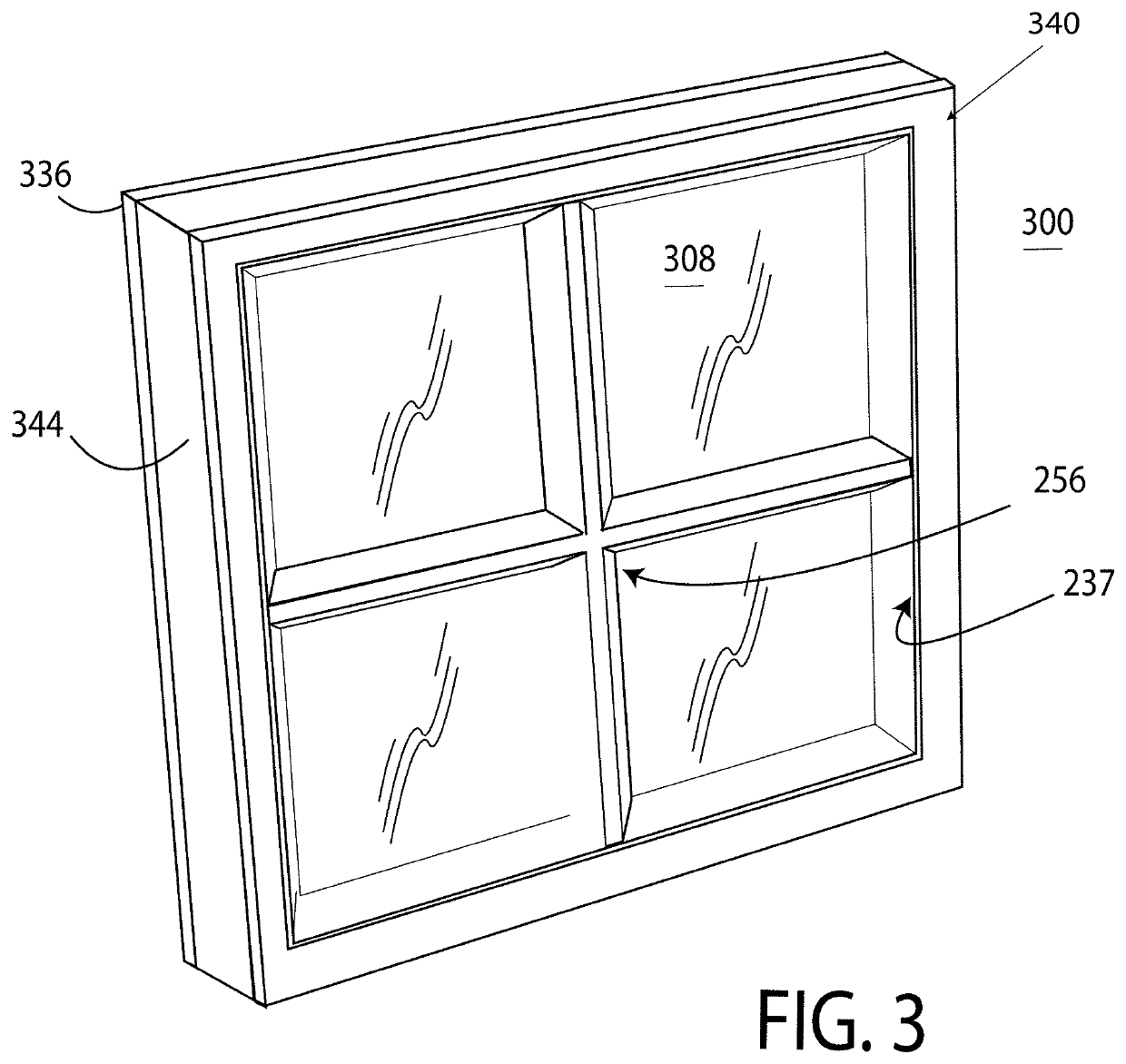
CROSS REFERENCE TO RELATED APPLICATIONS[0001]This application is not related to any other applications on the date of filing.FIELD OF THE INVENTION[0002]The disclosure relates generally to door systems, window systems, and methods for making door systems and window systems. The disclosure relates more particularly to door systems and window systems having an element including a metal frame assembly and insulated glass pane.BACKGROUND OF THE INVENTION[0003]Door systems and window systems (collectively “door systems”) may include a fixed casement framing the portal, and a door body or element supported for swinging movement relative to the casement. Window systems may be of similar construction, with the window element typically being fixed in the casement. The casement, for example, may be formed primarily of metal or wood and may include weather-stripping. The door element or window element (collectively “element”) may include a metal frame assembly and an insulated glass pane mount...

Claims


Application Information

Patent Timeline
Patent Type & Authority Patents(United States)
IPC IPC(8): E06B3/12E06B3/54E06B3/24E06B3/58E06B3/263
CPCE06B3/5892E06B3/549E06B3/263E06B3/24E06B3/5814E06B3/12E06B2003/2631E06B2003/26309E06B3/68
Inventor MEDINA, MARTHASALMERON, MISRRAIM CARDENASSALAS, ALEJANDRO SALAZAR
Owner PORTELLA IND LLC
Learn More