Multi-voltage level power supply system

a power supply system and multi-voltage technology, applied in secondary cell servicing/maintenance, instruments, final product manufacturing, etc., can solve the problems of shortening the general life expectancy of the battery, the need for more than energy storage devices, and the battery cells carrying out unégal work, so as to save weight and the required accommodation space, and the battery capacity is high. , the effect of different aging distribution over tim

Inactive Publication Date: 2005-09-29
FORD GLOBAL TECH LLC
View PDF1 Cites 25 Cited by
  • Summary
  • Abstract
  • Description
  • Claims
  • Application Information

AI Technical Summary

Benefits of technology

[0006] An advantage of the present invention is to use a single battery which allows the energy required for a starting process to be provided in all circumstances. In addition to this, it should be possible to switch to a parallel arrangement when a high battery capacity is required.
[0007] Advantageously, the present system includes a 12 V electrical energy storage capability (for the 14V bus) and storage functionality for 36 V devices (for the 42V bus). This avoids the need for a separate 12 V battery, thus saving weight and the required accommodation space. Ideally, the accommodation space requirement for a 36 V device for energy storage would remain the same in comparison with the accommodation space requirement for a 36 V battery in a two-battery arrangement. Because a 36 V battery can be regarded as three series-connected 12 V batteries, the 12 V energy storage function may be provided by the provision of three positive battery poles (e.g., 12 V, 24 V, 36 V) as well as the battery ground.
[0008] However, there exist two problems in designing an arrangement as proposed. On the one hand, differences occur in the states of charge of the various cells in the battery, because the battery is charged at a 42 V level and energy is additionally drawn from those cells which provide the functionality for the 12 V part of the electrical energy storage. Secondly, this additional discharging of these cells by the 14 V part of the power network (if no DC / DC converters are available) results in the battery cells carrying out unequal work, so that they have a different aging distribution over time. Since this will shorten the general life expectancy of the battery, a change to this approach is required for the electrical two-voltage power supply system.
[0009] In order now to avoid aging of only some of the cells in the 36 V battery, it is necessary in addition to distribute the drawing of electrical energy from the battery over the various cells. In the following text, the 36 V battery is therefore regarded as three separate 12 V parts in a common housing. In this regard, an objective is to ensure that each 12 V part is switched alternately in order to incorporate the 12 V energy storage functionality as part of the electrical 36 V power supply system.
[0010] In this context, EP 1 295 757 A2 discloses a power supply system for vehicles having an energy source for supplying electrical power to a large number of electrical load groups, each at different voltage levels. In this case, a large number of load elements form each electrical load group, and a large number of output means are provided in order to deliver the electrical power for each predetermined voltage as a medium voltage from the energy source. In this case, the large number of output means are arranged in the energy source, with the large number of load elements being distributed between a number of blocks in each load group and being connected to each output element in order to ensure that the electrical energy which is being consumed simultaneously by each distributed block is essentially the same. This power supply system is intended to improve the charge equalization in the battery without having to use a special battery indication and monitoring device or a DC / DC converter, and with the desired medium voltage being delivered from the high-voltage battery.
[0011] In a modified embodiment of this implementation, the system has an energy source for supplying electrical power to an electrical load group at a low voltage and to an electrical load group at a high voltage. The energy source in this case has output connections at the ends, which are connected to the electrical load group at a high voltage, as well as a large number of central output connections in order to deliver the electrical energy for the electrical load group at the low voltage as a medium voltage from the energy source. In this case, the electrical load group at the low voltage is subdivided into a large number of blocks which are connected in an appropriate manner to each output and to the large number of central output connections, in order to allow the electrical energy which is consumed at the same time by each block to be essentially the same and, furthermore, with one of the blocks which are distributed in the electrical load group at the low voltage being set such that it has more load than the other blocks.

Problems solved by technology

However, one disadvantage of is the need for more than energy storage device in order to accommodate the energy requirements for high power output loads.
However, there exist two problems in designing an arrangement as proposed.
Secondly, this additional discharging of these cells by the 14 V part of the power network (if no DC / DC converters are available) results in the battery cells carrying out unequal work, so that they have a different aging distribution over time.
Since this will shorten the general life expectancy of the battery, a change to this approach is required for the electrical two-voltage power supply system.
However, as a result of the addition of new functions such as electrical devices to assist starting of an engine and to assist its acceleration, such as electrically assisted steering, electrical braking and / or electrical suspension damping systems which are intended to be integrated in the relevant vehicle, the electrical capacity when using 12 V batteries is not sufficient to support these functions.
However, from the technical and financial points of view, a large amount of effort is required to provide only the 42 V power supply system which is intended to interact with all of the electrical devices in the vehicle, such as the valves for low voltage or the control devices with an electronic control unit.
Furthermore, in the case of a solution such as this, the total charge intensity is too low for a 42 V load group.
However, in the known solutions, the superimposition of the charging currents of the 36 V battery part and of the 12 V battery part have resulted in a problem in that the 12 V battery part is not only excessively discharged but that also this discharging of the 12 V battery part makes it necessary to provide an indication and control of the charging currents, for example by means of a costly DC / DC converter.
However, an arrangement such as this is difficult when using electrical two-voltage energy storage systems within an electrical two-voltage system.
This necessitates a new cable harness arrangement for each 14 V charging process, because this cannot be directly connected to the vehicle chassis.

Method used


Image

  • Multi-voltage level power supply system
  • Multi-voltage level power supply system
  • Multi-voltage level power supply system

Examples


Embodiment Construction

)

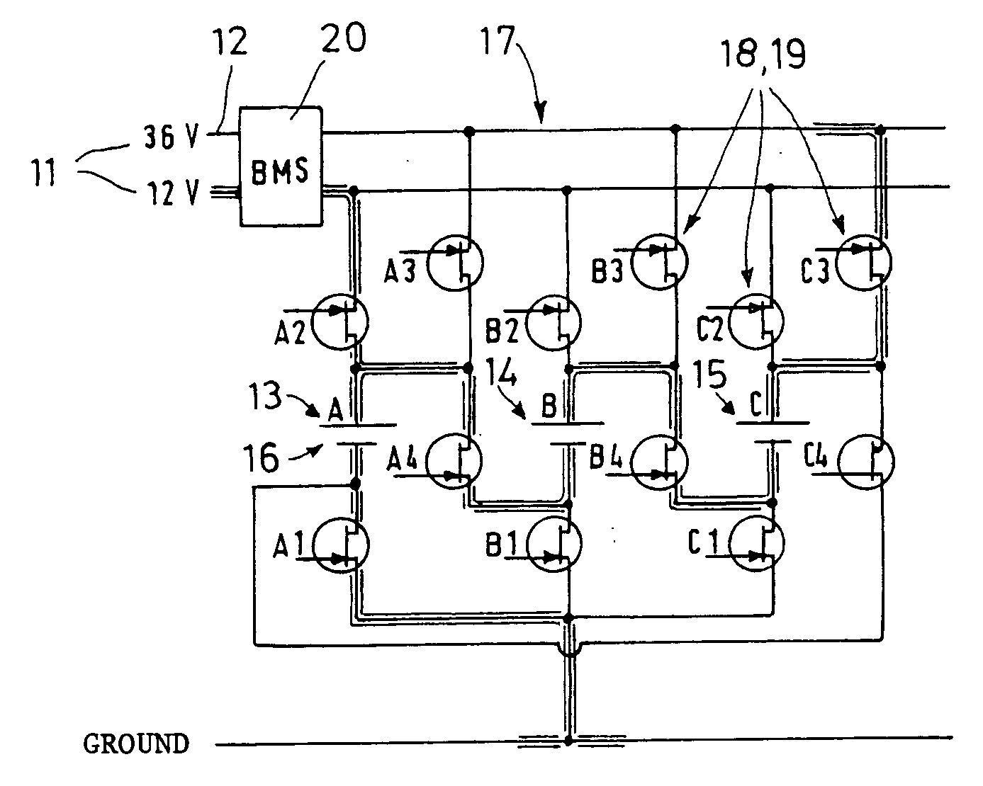
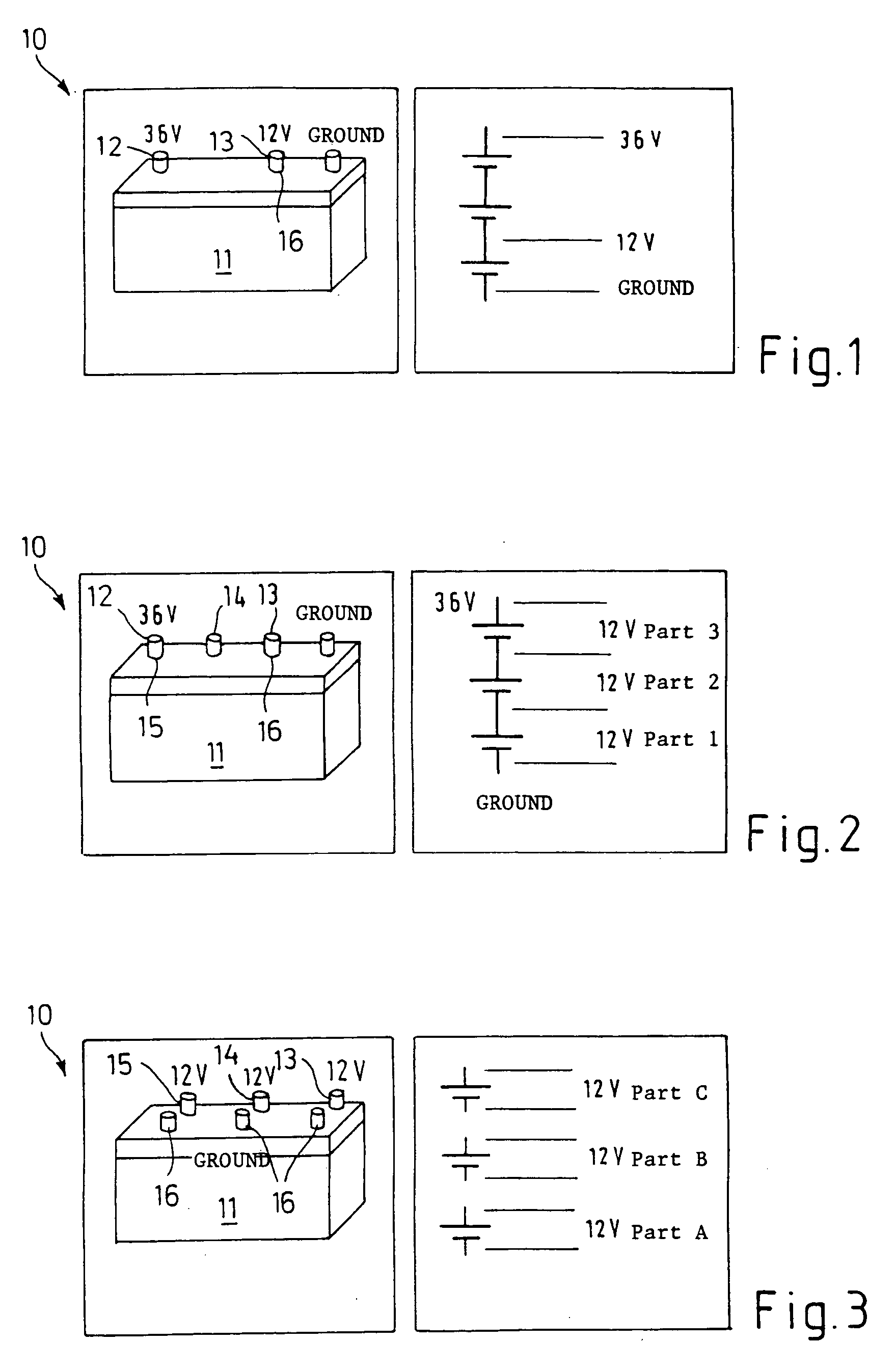
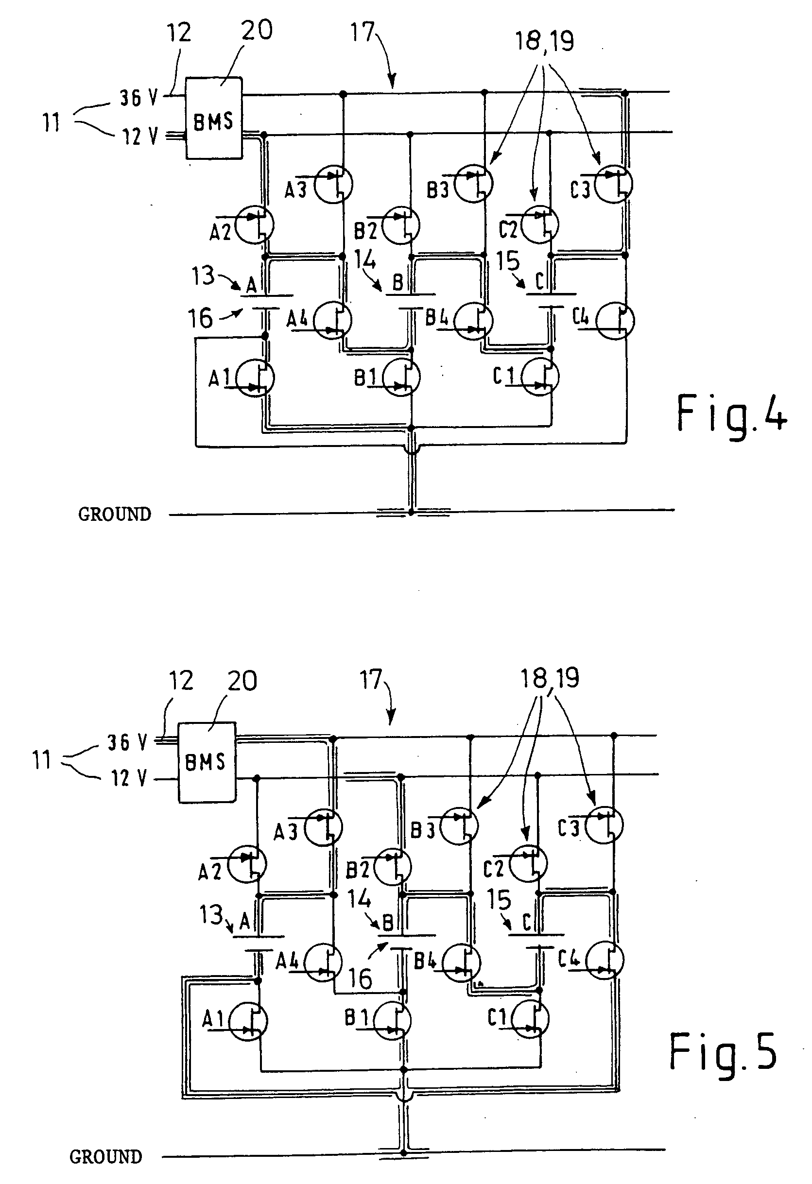
[0040] The power supply system according to the invention is annotated in general by 10. For this purpose, the power supply system 10 is illustrated in the form of a number of fundamental concepts, which are still to be explained, in FIGS. 1 to 3 of the drawing. The power supply system 10 is intended for vehicles with a two-voltage storage system, comprising an electrical 14 / 42 V two-voltage system, which is annotated 11, with a 36 V battery 12, which essentially has three alternately switchable 12 volt batteries 13, 14, 15, of which one can be connected as the first 12 volt part 16 between ground and 12 V, and with the respective devices for energy storage for the 14 V and 42 V system, with the 36 V battery 12 including the device for energy storage for the 12 V system and the device for energy storage for the 42 V system.

[0041] Various power supply systems 10 for vehicles with a two-voltage storage system and which have a 14 / 42 V electrical two-voltage system 11 are known in thi...


PUM

PropertyMeasurementUnit
voltageaaaaaaaaaa
voltageaaaaaaaaaa
voltageaaaaaaaaaa

Abstract

A multi-voltage power supply system, such as a 14V/42V dual-voltage system for vehicular applications, includes a battery arrangement and an intelligent switching regulator for providing at least a first output at a first potential and a second output at a second potential higher than the first potential. The battery arrangement includes a plurality of segments each providing an output substantially equal to the first potential. The switching regulator selectively conFIG. s each of the segments as a first part having a potential difference determined with respect to the first potential and a reference potential, e.g., ground, such that the power supply system provides the first and second outputs while minimizing degradation of the segments.

Description

BACKGROUND OF THE INVENTION [0001] 1. Field of the Invention [0002] The invention relates to a multi-voltage power supply system, and more specifically to a dual-voltage power supply system for vehicles having a two-voltage storage system such as a 14 / 42 V two-voltage system. [0003] 2. Background Art [0004] Multi-voltage level power supply systems, such as 14 / 42 V two-voltage (“dual voltage”) systems, are known in the art. In the case of 14 / 42 V systems, such systems have been developed in order to facilitate the transition from a conventional 14 V electrical system to an electrical system operating at a 42 V level. However, one disadvantage of is the need for more than energy storage device in order to accommodate the energy requirements for high power output loads. [0005] In a conventional automotive, for a example, a single 12 V battery is used as the device for energy storage for the 14V bus. However, in many applications for 14V / 42V systems, it is often necessary to use two sep...

Claims


Application Information

Patent Timeline
Patent Type & Authority Applications(United States)
IPC IPC(8): B60R16/02B60R16/03H01M6/42H01M10/04H01M10/44H02J1/08H02J7/00H02J7/14
CPCB60R16/03H01M6/425H01M10/0413H02J2001/008H01M10/44H02J1/08H01M10/0445H02J1/082H02J2310/46Y02E60/10Y02P70/50
Inventor LEYTEN, MAXGAEDT, LUTZ
Owner FORD GLOBAL TECH LLC
Why Eureka
Try Eureka