Stackable block for insulating concrete form system

a technology of concrete form and stackable foam, which is applied in the direction of walls, building components, construction materials, etc., can solve the problems of product wastage, block only being used in one orientation, and particularly faced with wastag

Inactive Publication Date: 2005-10-13
PLASTI FAB
View PDF9 Cites 41 Cited by
  • Summary
  • Abstract
  • Description
  • Claims
  • Application Information

AI Technical Summary

Benefits of technology

[0010] In another aspect, the invention provides an insulating concrete form block made of a pair of foam panels spaced apart by two or more ties and wherein the panels are provided with interlocking means to enable vertically and horizontally adjacent blocks to engage each other and an alignment means to ensure vertical alignment of the ties. The interlocking means of each panel are arranged opposite to the other of the block so as to allow the block to be reversible, or used in either vertical orientation.
[0011] In another aspect, the invention provides an insulating concrete form block comprising a pair of foam panels separated by two or more ties, wherein each of the panels has an interlocking means for engaging neighbouring blocks, and wherein the block has a first plane of symmetry extending diagonally between the top of one panel to the bottom of the other panel and a second plane of symmetry extending diagonally between the top right corner to the bottom left corner of the block. The panels of the block are provided with an alignment means to ensure vertical alignment of the ties when the blocks are stacked.
[0012] In another aspect, the invention provides a reversibly stackable insulating concrete form block, for use in a concrete form system, comprising: first and second foam panels, arranged opposed and parallel to each other and spaced apart by a predetermined distance; and two or more ties extending perpendicularly between the panels to maintain the panels in the spaced apart orientation. In each panel, its top and bottom edges and left and right ends have: a) a first interlocking means for engaging a respective panel of a block vertically adjacent thereto; b) a second interlocking means for engaging a respective panel of a block located horizontally adjacent thereto; and c) a tie aligning feature for vertically aligning ties of vertically adjacent blocks. In the block, the panels of the block are arranged in opposite orientation with respect to each other whereby the block can be engaged with other vertically adjacent blocks in either a right-side up or upside-down orientation.
[0013] In another aspect, the present invention provides a reversibly stackable insulating concrete form block, for use in a concrete form system, comprising: first and second foam panels, arranged opposed and parallel to each other and spaced apart by a predetermined distance; and two or more ties extending perpendicula...

Problems solved by technology

One of the problems associated with some known ICF block systems is that the blocks can only be used in one orientation.
This often results in wastage of product.
Such wastage is particularly faced when a...

Method used


Image

  • Stackable block for insulating concrete form system
  • Stackable block for insulating concrete form system
  • Stackable block for insulating concrete form system

Examples


Embodiment Construction

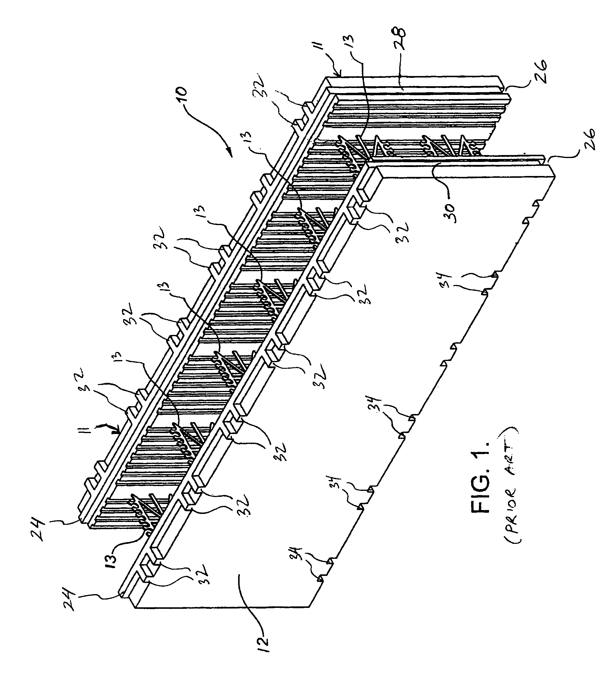
[0027]FIG. 1 illustrates a prior art form block as described, for example, in U.S. Pat. No. 5,896,714. As shown, the block 10 comprises opposing panels 11 and 12 made of an insulating foam material as will be known to persons skilled in the art. The panels 11 and 12 are joined together by means of a plurality of ties 13 extending there-between. The panels 11, 12 are maintained in an aligned and parallel manner, with the ties 13 extending perpendicularly between the panels. As shown in FIG. 1 and as known in the art, the facing surfaces of each panel 11 and 12 are preferably provided with a plurality of grooves so as to form a stronger bond with the concrete.

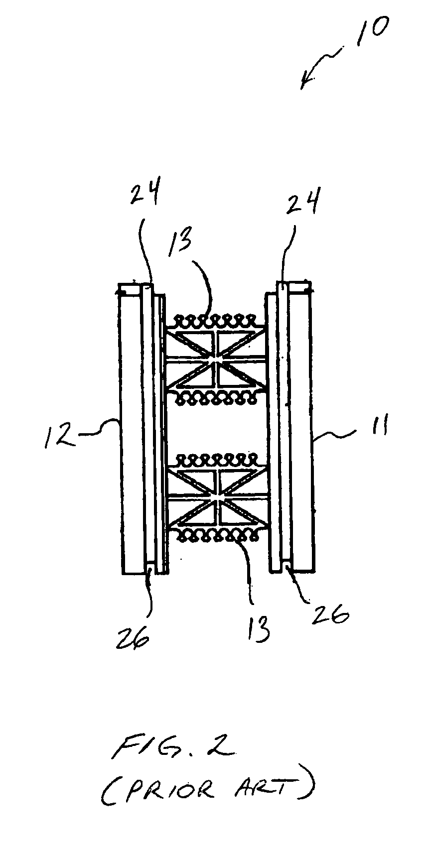
[0028]FIG. 2 illustrates an end view of the block of FIG. 1 and more clearly illustrates the tongues 24 and grooves 26 of the prior art form block. FIG. 2 also illustrates the ties 13 as known in the art. The ties comprise a central, planar web portion and two flanges on opposite ends of the web portion. The flanges are embedded...


PUM


Abstract

A concrete form system comprising a reversibly stackable insulating form blocks each block having a pair of panels separated by two or more ties. Each of the top, bottom and side edges of the panels includes either a tongue or groove so as to engage a corresponding tongue or groove of a panel of another block stacked vertically or horizontally adjacent thereto. The panels of each block are arranged in opposite orientation to each other so as to enable the block to be stackable in either an upside-down or right-side-up orientation.

Description

RELATED APPLICATION [0001] This application claims the benefit of U.S. Provisional Application No. 60 / 555,956 filed on Mar. 25, 2004.FIELD OF THE INVENTION [0002] The present invention relates to concrete form systems and, more specifically, to systems comprised of stackable foam block units. More particularly, the invention relates to insulating concrete form blocks that are reversibly stackable. BACKGROUND OF THE INVENTION [0003] In the field of constructing concrete walls, it is commonly known to use forms normally comprising a pair of panels arranged parallel to one another and separated by a distance. Concrete is then poured between the panels and allowed to set. After the concrete is set, the panels, usually made of wood, are removed. It is common to have ties extending between the two panels to ensure that the desired spacing is maintained. [0004] The advent of insulating concrete form (ICF) systems has provided an improvement in concrete form systems. In ICF systems, the pan...

Claims


Application Information

Patent Timeline
IPC IPC(8): E04B2/00E04B2/02E04B2/86E04C1/41
CPCE04B2/8635E04B2002/0204E04B2002/0206E04B2002/867E04C1/41
Inventor CYMBALA, PATRICK M.DOREN, GREGORY J.
Owner PLASTI FAB
Why Eureka
Try Eureka