Electrical connection box

a technology of electrical connection and box body, which is applied in the direction of coupling device connection, coupling contact member, coupling base/case, etc., can solve the problems of difficult positioning of plural terminals at the same time, large control circuit substrate size, etc., and achieve the effect of avoiding short circuit between terminals

Inactive Publication Date: 2005-10-13
AUTONETWORKS TECH LTD +2
View PDF5 Cites 57 Cited by
  • Summary
  • Abstract
  • Description
  • Claims
  • Application Information

AI Technical Summary

Benefits of technology

[0016] Since a part of one terminal fitted with another terminal is accommodated into a hole-like space of the positioning part, short-circuiting between the terminals can be avoided without fail even in a case where the terminals are arrayed in a line.

Problems solved by technology

Therefore, a larger number of branch circuits and poles used in the electric power conducting channel will inevitably require a greater space for installing electric power conducting channels, resulting in a larger-sized control circuit substrate.
It is, however, difficult to position plural terminals at the same time.

Method used


Image

  • Electrical connection box
  • Electrical connection box
  • Electrical connection box

Examples


Embodiment Construction

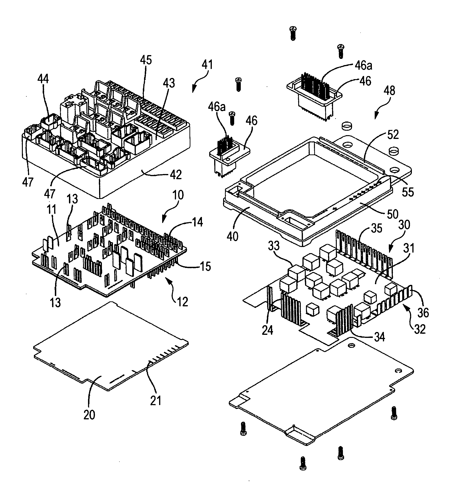
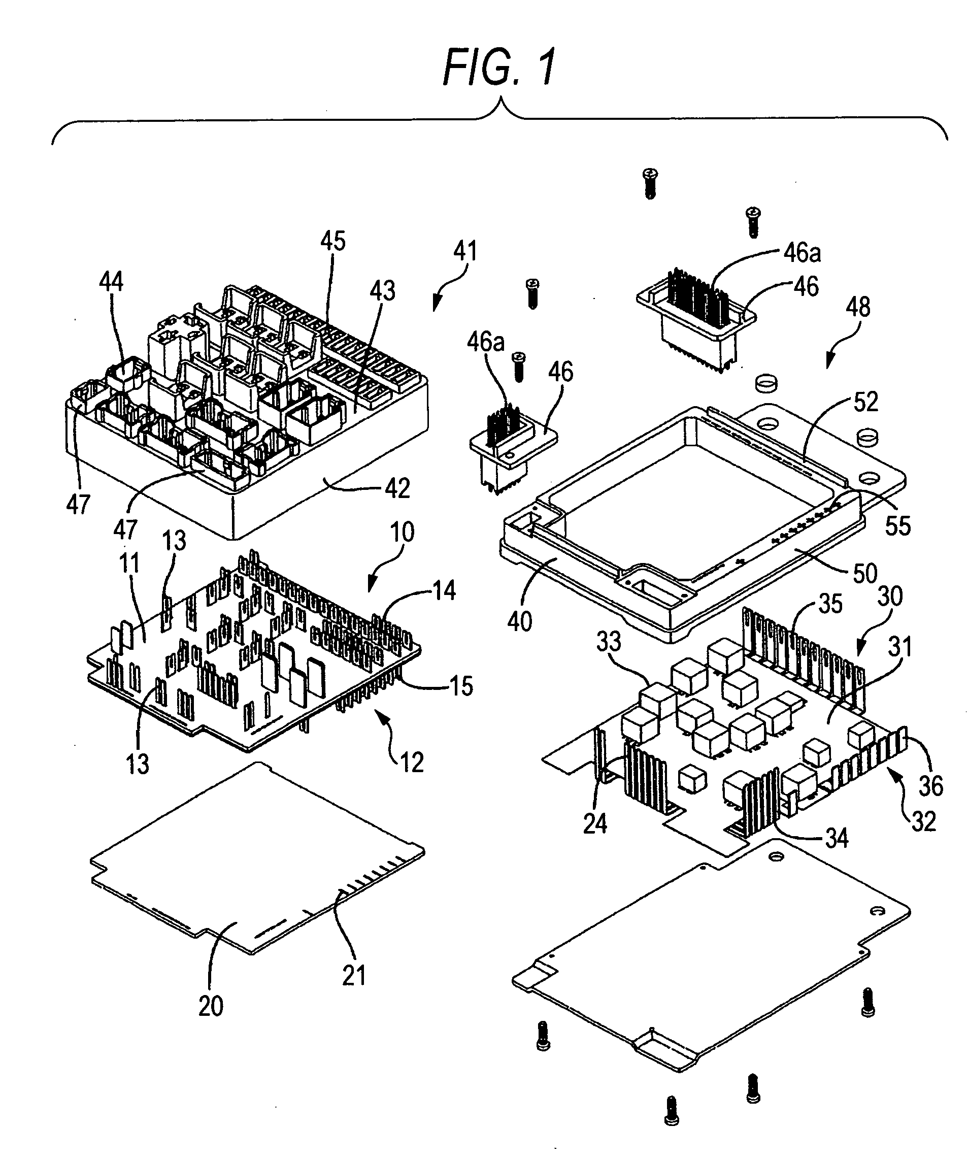
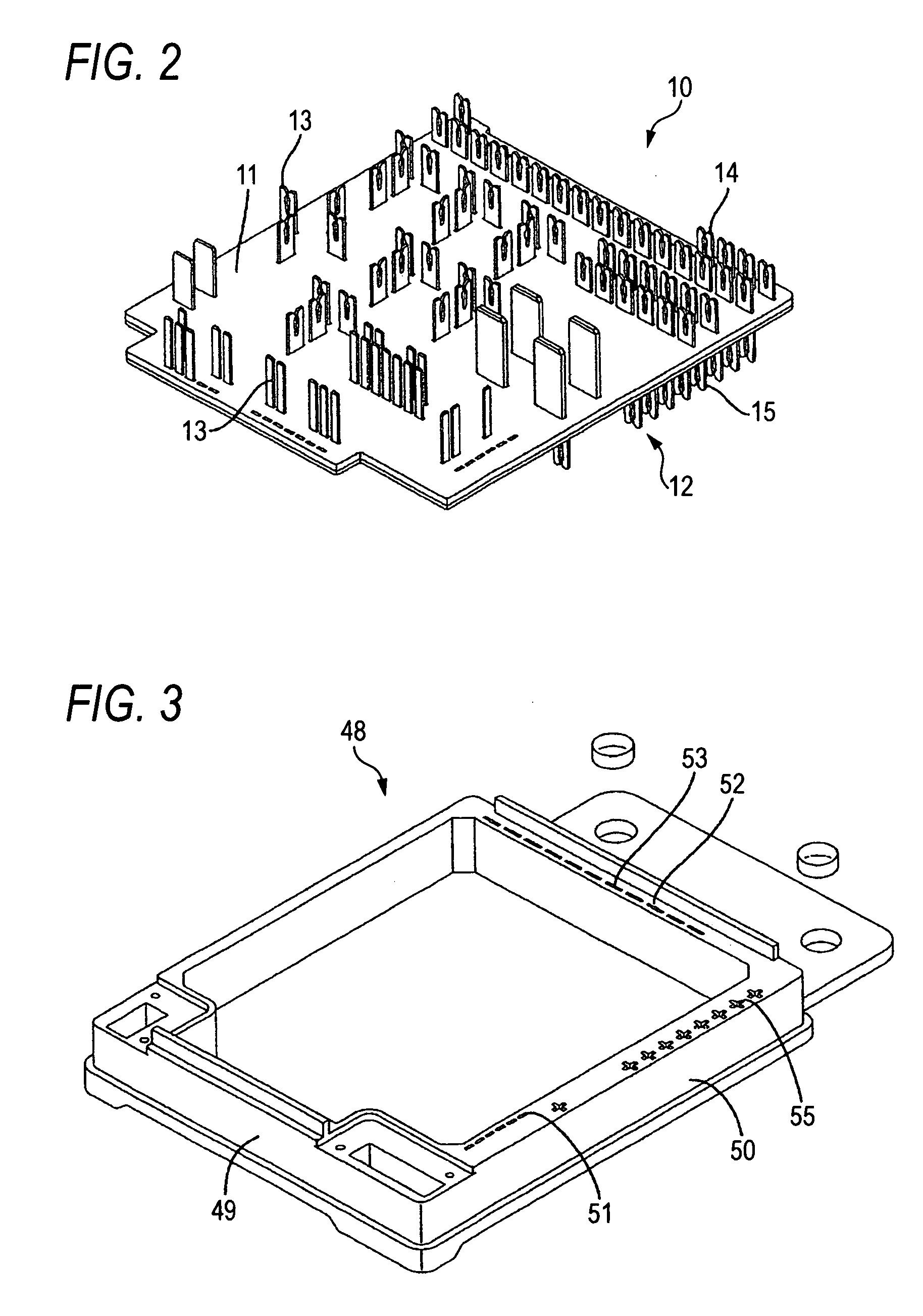
[0026] Hereinafter, a concrete embodiment 1 of the present invention is described by referring to FIG. 1 through FIG. 9. In the electrical connection box of this embodiment, the first circuit component 10 and the second circuit component 30 are accommodated in the case 40 in such a way that they are overlapped one above the other horizontally.

[0027] The first circuit component 10 is provided with an approximately rectangular supporting substrate 11, the first electric power conducting channel 12 arrayed along the supporting substrate 11 and a relay (not illustrated) fixed on the upper cover 41 to be described later. The first electric power conducting channel 12 includes plural pass bars made with a thick metal sheet punched out into a predetermined shape. The first electric power conducting channel 12 is formed in an integrated form with plural relay terminals 13 penetrating through the supporting substrate 11 and projecting on the upper plane (surface) at an approximately right a...


PUM


Abstract

A case accommodates two circuit components to be overlapped one above the other and mutually in an approximately parallel form. The terminals of the upper electric power conducting channel are fitted into the terminals of the lower electric power conducting channel one above the other so that they can be connected. The case is provided with a positioning part which regulates deflection of both the terminals above and below toward the vertical direction intersecting with the direction that the terminal is fitted into the terminal, thus making it possible to give positioning to a plurality of the terminals all together and also making it possible to connect the terminals and the terminals respectively to their counterparts without fail. Further, the positioning part is provided on the case for accommodating the circuit components, which eliminates the necessity for a special positioning member.

Description

BACKGROUND OF THE INVENTION [0001] 1. Field of the Invention [0002] The present invention relates to an electrical connection box. [0003] 2. Description of the Related Art [0004] As disclosed in JP-A-2003-164039, known is an electrical connection box constructed with a control circuit substrate, a switching member arrayed on the surface of the control circuit substrate and controlled by the control circuit substrate and an electric power conducting channel arrayed on the back of the control circuit substrate and connected with a power source. SUMMARY OF THE INVENTION [0005] Since a relatively large electric current flows through an electric power conducting channel in this type of electrical connection box, it is structured to occupy a larger installation space such as broader metal plates. Therefore, a larger number of branch circuits and poles used in the electric power conducting channel will inevitably require a greater space for installing electric power conducting channels, re...

Claims


Application Information

Patent Timeline
Patent Type & Authority Applications(United States)
IPC IPC(8): H01R13/46H01R4/48H01R9/24H01R13/11H01R13/115H02G3/16
CPCH01R13/113H01R9/2466
Inventor YAMASHITA, HISANOBUMIYAZAKI, KUNIHIROMIYAMOTO, TAKASHIEJIMA, TAKUMI
Owner AUTONETWORKS TECH LTD
Why Eureka
Try Eureka