Ferrite core, method of manufacturing the same, and common-mode noise filter using the same

a technology of ferrite core and ferrite core, which is applied in the direction of inductance, inductance with magnetic core, basic electric elements, etc., can solve the problems of reducing the adhesion properties of the ferrite core, further reducing the adhesion properties, so as to prevent short-circuit and avoid damage.

Active Publication Date: 2005-03-10
KYOCERA CORP
View PDF3 Cites 47 Cited by
  • Summary
  • Abstract
  • Description
  • Claims
  • Application Information

AI Technical Summary

Benefits of technology

[0025] The present invention is made to solve the above problems and it is an object of the present invention to provide a ferrite core and a common-mode filter each of which has a structure in that plating is prevented from elongating, which can maintain insulation resistance between electrodes and can prevent short-circuit between a conductor wire and the electrode without damaging adhesion properties while mounted and, moreover, which can stabilize a Q value (loss characteristic) of a product.

Problems solved by technology

In addition, in a field of information communication devices in which the common-mode noise filter is used, there are demands for smaller and lighter components.
However, in the filed of information communication devices in which such common-mode noise filter is used, there are demands for further smaller and lighter components in accordance with miniaturization of the device.
That is, when the electrode 903 is formed on the top surface of the leg 902, there is a problem such that the plating elongates along a boundary part (vertical corner portion) between the side faces of the leg.
When the plating elongates along the vertical corner portion, it becomes difficult to acquire insulating properties as the component becomes smaller.
According to a structure of the conventional common-mode noise filter, in the case of the size of 3.2 mm by 1.6 mm, for example, even when the plating of the electrode 903 elongates as described above, since the distance between electrodes 903 of the legs 902 is kept at about 0.6 mm, insulating properties can be remained, but when the size becomes smaller, it becomes difficult to acquire the insulating properties.
In addition, although it is preferable to increase the thickness of the electrode 903 in order to acquire mounting strength when the common-mode filter is mounted on a substrate, since the plating elongates along the vertical corner portion in the conventional structure, there is a limitation in forming thickly the plate layer and it is difficult to sufficiently acquire the mounting strength.
Furthermore, as shown in FIG. 6, there is a problem such that the conductor wire connected to one electrode 903 of the adjacent legs comes in contact with the plated layer elongated along the vertical corner portion of the other leg to cause a short-circuit.
Furthermore, since the dimensions of the electrodes 903 vary because of the elongation of the plating, there is a problem such that loss of a magnetic flux generated at the ferrite core 6 varies and a Q value (loss characteristic) is liable to vary.
Still further, according to the common-mode noise filter using the ferrite core disclosed in Japanese Patent No. 3168972, there is a problem such that the area of the top surface of the leg 952 is decreased because the inclined surface is provided at the leg 952, so that adhesion strength when mounted is lowered.

Method used


Image

  • Ferrite core, method of manufacturing the same, and common-mode noise filter using the same
  • Ferrite core, method of manufacturing the same, and common-mode noise filter using the same
  • Ferrite core, method of manufacturing the same, and common-mode noise filter using the same

Examples


example 1

[0207] According to Example 1, evaluations were made on 15 kinds of samples provided such that sintered bodies of original forms of the ferrite porcelain which were manufactured in the same conditions were processed by a barreling process so that the tapered shapes of the legs 2 and the curved-surface shapes of the vertical corner portions of the legs 2 might be different from each other. The tapered shapes of the legs 2 and the curved surface shapes of the vertical corner portions were varied by adjusting an amount of polishing agent, the number of sintered bodies to be processed and a processing time.

[0208] According to Example 1, an Ni—Zn ferrite material as a magnetic material and a binder were mixed and raw powder was manufactured by spray drying.

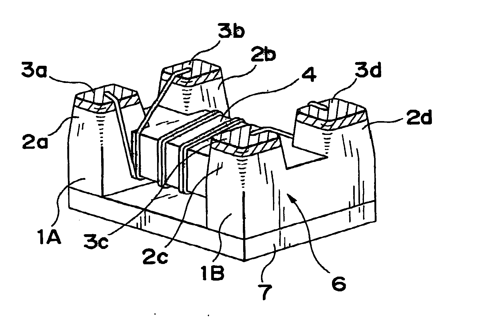
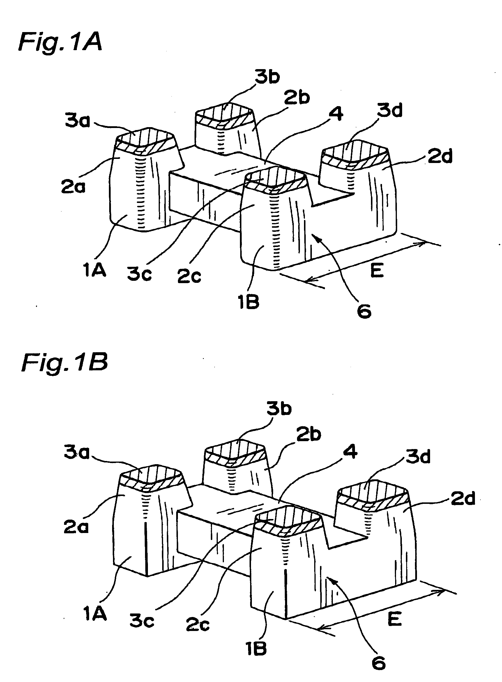
[0209] Then, this raw powder was molded so as to provide the original form of the ferrite core 6 of the present invention as shown in FIGS. 1A and 1B by powder-press molding, and then burned at 900 to 1300° C. to manufacture many sin...

example 2

[0225] According to Example 2, except that only water was used as the polishing agent, similar to Example 1, the barreling process were performed under the various conditions and a leg 2 was formed into the shape shown in Table 2 and an electrode 3 was formed on a top surface thereof.

[0226] In addition, the shape of the leg 2 of each ferrite core sample was measured by a measuring microscope.

[0227] Then, similar to Example 1, the evaluations (1) to (3) were made for each ferrite core sample provided.

[0228] Besides, 30 ferrite cores were prepared for each sample No. and a conductor wire having a diameter of 0.1 mm were wound by 7 turns and the evaluation (4) was made similar to Example 1.

[0229] In addition, 30 ferrite cores were prepared for each sample No. and a conductor wire of 0.1 mm in diameter was wound around the ferrite core and the evaluation (4) was made similar to Example 1.

[0230] Their results are shown in Table 2.

Table 2Shape of legCurvatureCurvatureEvaluationradi...

example 3

[0235] According to Example 3, the ferrite core 56 of the present invention shown in FIG. 8 is manufactured.

[0236] First, Ni—Zn ferrite as a magnetic material and a binder were mixed and raw powder was manufactured by spray drying.

[0237] Then, a die divided into a wound core 5 and legs 52a to 52c and 62a to 62c was manufactured and after it was set in a powder-press molding machine, the raw power was put therein and molded.

[0238] Then, it was burned at 900 to 1300° C. to manufacture a sintered body of the original form of the ferrite porcelain having four legs 52a, 52c, 62a and 62c. Thus, 20 sintered bodies were manufactured.

[0239] At this time, maximum lengths of the legs 52a, 52c, 62a and 62c were set as follows.

[0240] The maximum length of the legs 52c and 62a: 0.4 mm

[0241] The maximum length of the legs 52a and 62c: 0.3 mm.

[0242] Then, the sintered bodies were put in the barreling device having a barrel-shaped container formed of a ferrite porcelain and the barreling proc...


PUM

PropertyMeasurementUnit
curvature radiusaaaaaaaaaa

Abstract

The present invention provides a ferrite core which has a structure in that plating is prevented from elongating, which can maintain insulation resistance between electrodes and can prevent short-circuit between a conductor wire and the electrode without damaging adhesion properties while mounted and, moreover, which can stabilize a Q value (loss characteristic) of a product. The ferrite core includes a wound core and flanges integrally formed at both ends of the wound core, and each of the flanges includes a plurality of legs provided so as to rise from one surface of the wound core and having a top surface to be formed with electrode, and each leg is tapered off toward the top surface and an vertical corner portion formed between adjacent side faces thereof has a curved surface.

Description

BACKGROUND OF THE INVENTION [0001] 1. Field of the Invention [0002] The present invention relates to a ferrite core suitable for measures for common-mode noise of various kinds of electronic devices in which a high-frequency signal is used, its manufacturing method, and a common-mode noise filter used in a differential transmission circuit and the like. [0003] 2. Description of the Related Art [0004] A common-mode noise filter is used for measures for unnecessary radiation of a power supply line or measures for a common-mode noise of a high-frequency signal. [0005] The common-mode noise filter is constituted such that a plurality of conductor wires are wound around a ferrite core 906 by several turns to some dozen turns. According to the conventional example disclosed in JP-A 2002-329618, as shown in FIGS. 3A-3C, the ferrite core 906 includes a ferrite porcelain having a wound core 904, flanges 901 provided at both ends thereof, and a plurality of legs 902 continued to the flanges 9...

Claims


Application Information

Patent Timeline
Patent Type & Authority Applications(United States)
IPC IPC(8): H01F17/04H01F27/29H03H1/00
CPCH01F27/292H01F17/045
Inventor SINGU, MASAMICHIWATARI, JUNICHI
Owner KYOCERA CORP
Why Eureka
Try Eureka