
Compact light emitting diode chip and light emitting device including the same

a light emitting diode and compact technology, applied in the direction of lighting and heating apparatus, printed circuit non-printed electric components association, instruments, etc., can solve the problems of deterioration in product reliability, tilting inability to change the shape of light emitting diodes, etc., to achieve low cost, high luminous efficiency, and low cost

Active Publication Date: 2017-04-20
SEOUL VIOSYS CO LTD
View PDF1 Cites 43 Cited by
  • Summary
  • Abstract
  • Description
  • Claims
  • Application Information

AI Technical Summary

Benefits of technology

The present patent provides a light emitting diode chip with high luminous efficacy and production yields while having a miniaturized area and thickness. Additionally, the patent provides a flip-chip type light emitting diode chip that prevents short circuits and reduces electrical characteristic deviation between produced chips. The patent also describes a light emitting device that includes a compact and slim light emitting diode chip mounted on a substrate via a bonding layer having a minimum thickness, thereby realizing a slim structure while securing good durability. Finally, the patent provides a light emitting diode chip and light emitting device that can prevent tilting upon mounting while securing product durability.

Problems solved by technology

However, since the light emitting diode is produced using, for example, gallium nitride-based single crystal semiconductors, the shape of the light emitting diode cannot be changed.
When the light emitting diodes are mounted on the leads using the solder, there can be a problem of tilting of the light emitting diodes due to flowability of the solder.
However, it is difficult to form the grooves on the leads on a flexible substrate such as an FPCB, and when the leads include the grooves thereon, disconnection is likely to occur upon deformation of a product, thereby causing deterioration in reliability of the product.
Moreover, when small light emitting diodes are arranged at narrow intervals, the grooves are formed in many regions on the leads, thereby further deteriorating product reliability.

Method used


Image

  • Compact light emitting diode chip and light emitting device including the same
  • Compact light emitting diode chip and light emitting device including the same
  • Compact light emitting diode chip and light emitting device including the same

Examples


Embodiment Construction

[0043]In the following description, for the purposes of explanation, numerous specific details are set forth in order to provide a thorough understanding of various exemplary embodiments. It is apparent, however, that various exemplary embodiments may be practiced without these specific details or with one or more equivalent arrangements. In other instances, well-known structures and devices are shown in block diagram form in order to avoid unnecessarily obscuring various exemplary embodiments.

[0044]In the accompanying figures, the size and relative sizes of layers, films, panels, ici regions, etc., may be exaggerated for clarity and descriptive purposes. Also, like reference numerals denote like elements.

[0045]When an element or layer is referred to as being “on,”“connected to,” or “coupled to” another element or layer, it may be directly on, connected to, or coupled to the other element or layer or intervening elements or layers may be present. When, however, an element or layer i...


PUM


Abstract

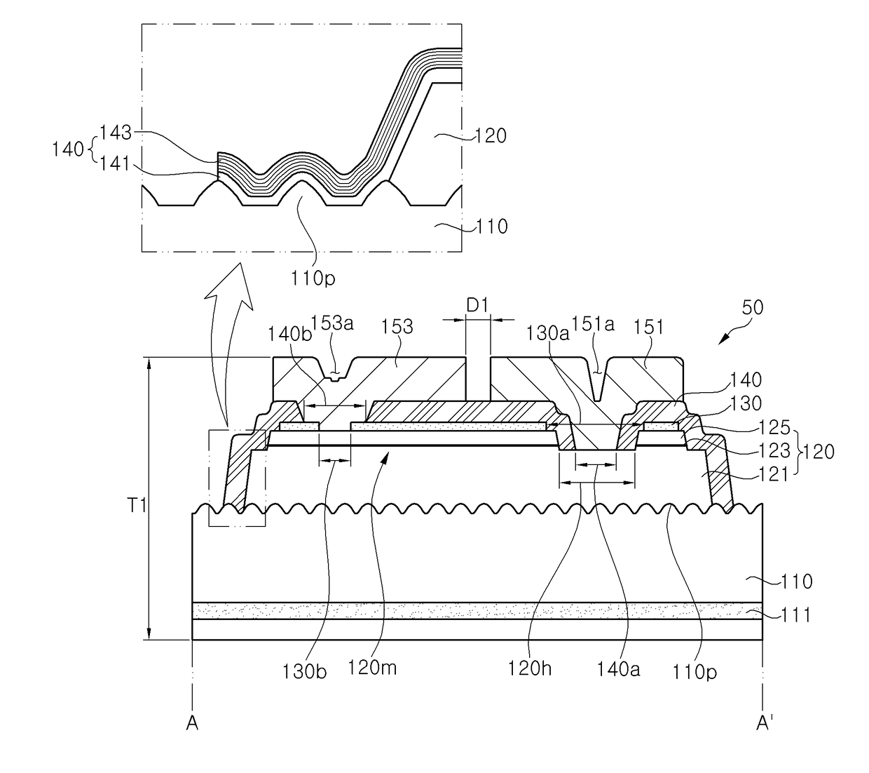
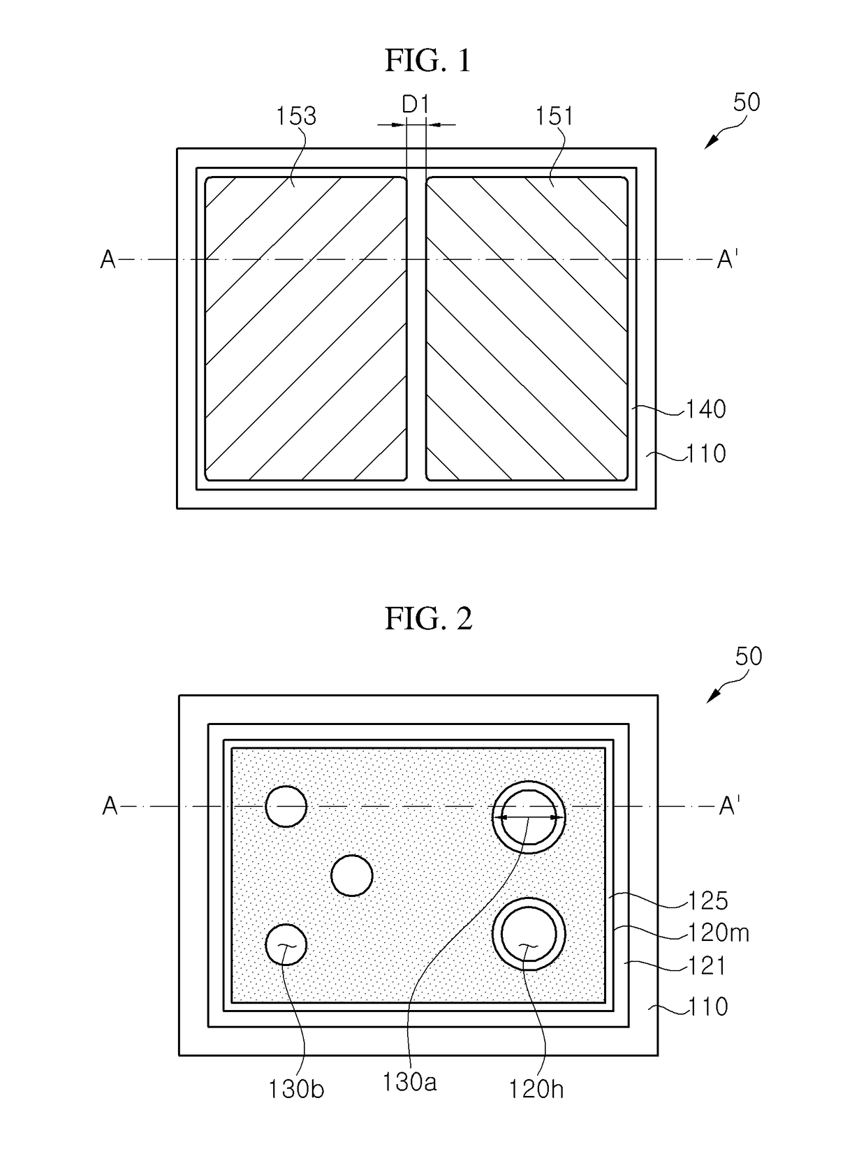
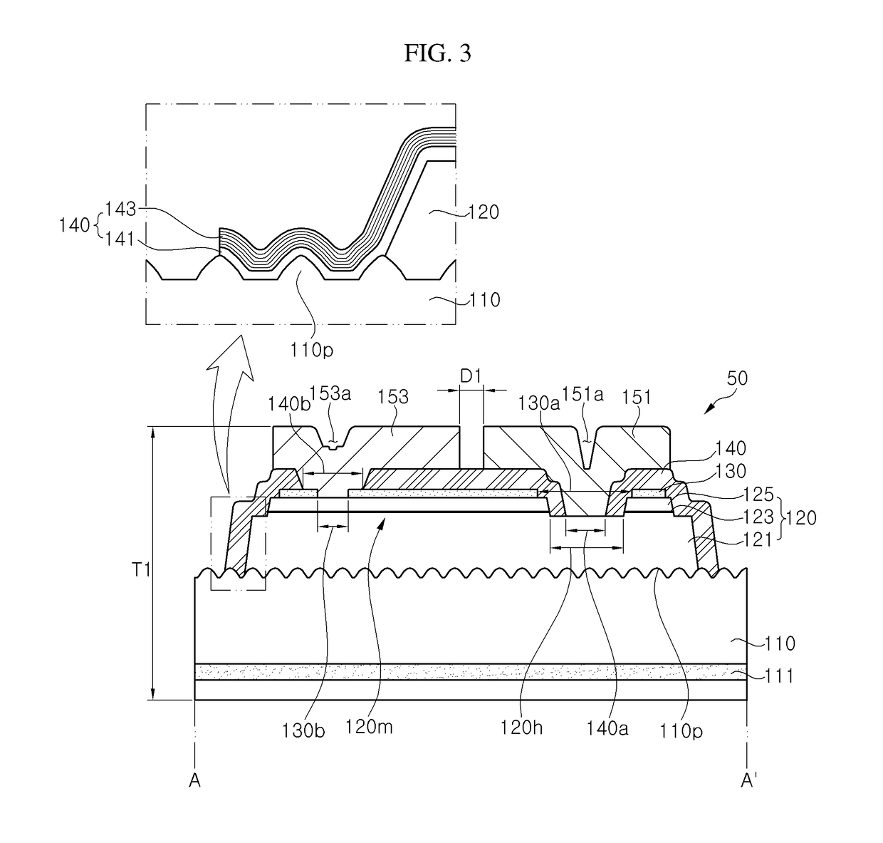
A light emitting diode chip includes: a first conductive type semiconductor layer disposed on a substrate; a mesa disposed on the first conductive type semiconductor layer and including an active layer and a second conductive type semiconductor layer; an insulation layer covering the first conductive type semiconductor layer and the mesa, the insulation layer including at least one first opening exposing the first conductive type semiconductor layer and a second opening disposed on the mesa; a first pad electrode disposed on the insulation layer and electrically connected to the first conductive type semiconductor layer through the first opening; and a second pad electrode disposed on the insulation layer and electrically connected to the second conductive type semiconductor layer through the second opening. The first opening of the insulation layer includes a first region covered by the first pad electrode and a second region exposed outside the first pad electrode.

Description

CROSS-REFERENCE TO RELATED APPLICATIONS[0001]This application is a continuation-in-part of U.S. application Ser. No. 15 / 279,549, filed Sep. 29, 2016, and claims priority to and the benefit of Korean Patent Application No. 10-2015-0144997, filed on Oct. 16, 2015, Korean Patent Application No. 10-2015-0181128, filed on Dec. 17, 2015, and Korean Patent Application No. 10-2016-0107578, filed on Aug. 24, 2016, all of which are hereby incorporated by reference for all purposes as if fully set forth herein.BACKGROUND[0002]Field[0003]Exemplary embodiments of the present disclosure relate to a compact light emitting diode chip, and a light emitting device including the same.[0004]Discussion of the Background[0005]Light emitting diodes are used in various products such as large back light units (BLUs), general lighting, electric products, small home appliances, and interior products.[0006]Light emitting diodes can be used not only as a light source, but also for various purposes including con...

Claims


Application Information

Patent Timeline
IPC IPC(8): F21K9/232H01L33/06H01L33/46H01L33/38F21S4/24H01L33/42H01L33/00H01L25/075H05K1/18H01L33/32H01L33/62
CPCF21K9/232H01L33/32H01L33/06H01L33/46H01L33/382H01L33/62F21Y2115/10H01L33/0033H01L25/0753H05K1/189F21S4/24H05K2201/10106G06F1/1662H01L33/42H01L2224/73204F21Y2107/70H01L33/0095H01L33/22H01L33/38H01L2933/0016H01L2933/0025H05K2201/0108
Inventor KIM, YE SEULKIM, KYOUNG WANWOO, SNAG WONKIM, JI HYE
Owner SEOUL VIOSYS CO LTD
Learn More