Antenna coil

a technology of antenna coil and shield, which is applied in the field of antenna coil, can solve the problems of reducing the transmission efficiency of the antenna coil, reducing and reducing the power supply efficiency too, so as to reduce the frequency of the transmission. the effect of the antenna coil and the reduction of the strength of the magnetic field

Inactive Publication Date: 2015-05-21
EQUOS RES
View PDF19 Cites 80 Cited by
  • Summary
  • Abstract
  • Description
  • Claims
  • Application Information

AI Technical Summary

Benefits of technology

[0015]Further, in the inventive antenna coil according to the present invention, preferably, the auxiliary coil portion is disposed such that of components of a current flowing in the auxiliary coil portion, a component parallel with the circumferential direction of the main coil portion has a same direction as a current flowing in the main coil portion on the side proximate to this main coil portion. With this arrangement, it becomes possible to restrict occurrence of reduction in the strength of the magnetic field generated by the main coil portion due to cancellation of the magnetic flux of the main coil portion by the magnetic flux of the auxiliary coil portion. It is therefore made possible to restrict reduction in the transmission efficiency of the antenna coil.
[0016]Also, preferably, at least one auxiliary coil portion is disposed along one axial end face of the main coil portion and has a smaller diameter than the main coil portion. Generally, the magnetic field formed around the main coil portion by current flowing in this main coil portion has a spreading in the direction along the first reference axis. With the above-described arrangement, the auxiliary coil portion is disposed along one axial end face of the main coil portion. By this auxiliary coil portion, of magnetic fluxes forming the magnetic field around the main coil portion and spreading in the direction along the first reference axis, magnetic flux which should travel from the one axial end face towards the outside along the first reference axis is guided by the auxiliary coil portion. With this, it becomes possible to provide the antenna coil with directivity favorably, with effective suppression of the magnetic field spreading along the first reference axis on this on axial side of the first reference axis. Further, as an axial coil portion having a smaller diameter than the main coil portion is employed in this arrangement, it is possible to restrict enlargement of the antenna coil.

Problems solved by technology

However, disposing a shield can sometimes be undesirable if disposing space or cost needs to be taken into consideration.
However, with such cancellation of magnetic fields, there occurs reduction in the strength of the magnetic field for a same amount of power supplied to the power supplying side resonance coil, so that reduction in power supply efficiency too occurs.
However, the addition of shield may lead to wasteful consumption of energy and deterioration in transmission efficiency.

Method used


Image

  • Antenna coil
  • Antenna coil
  • Antenna coil

Examples


first embodiment

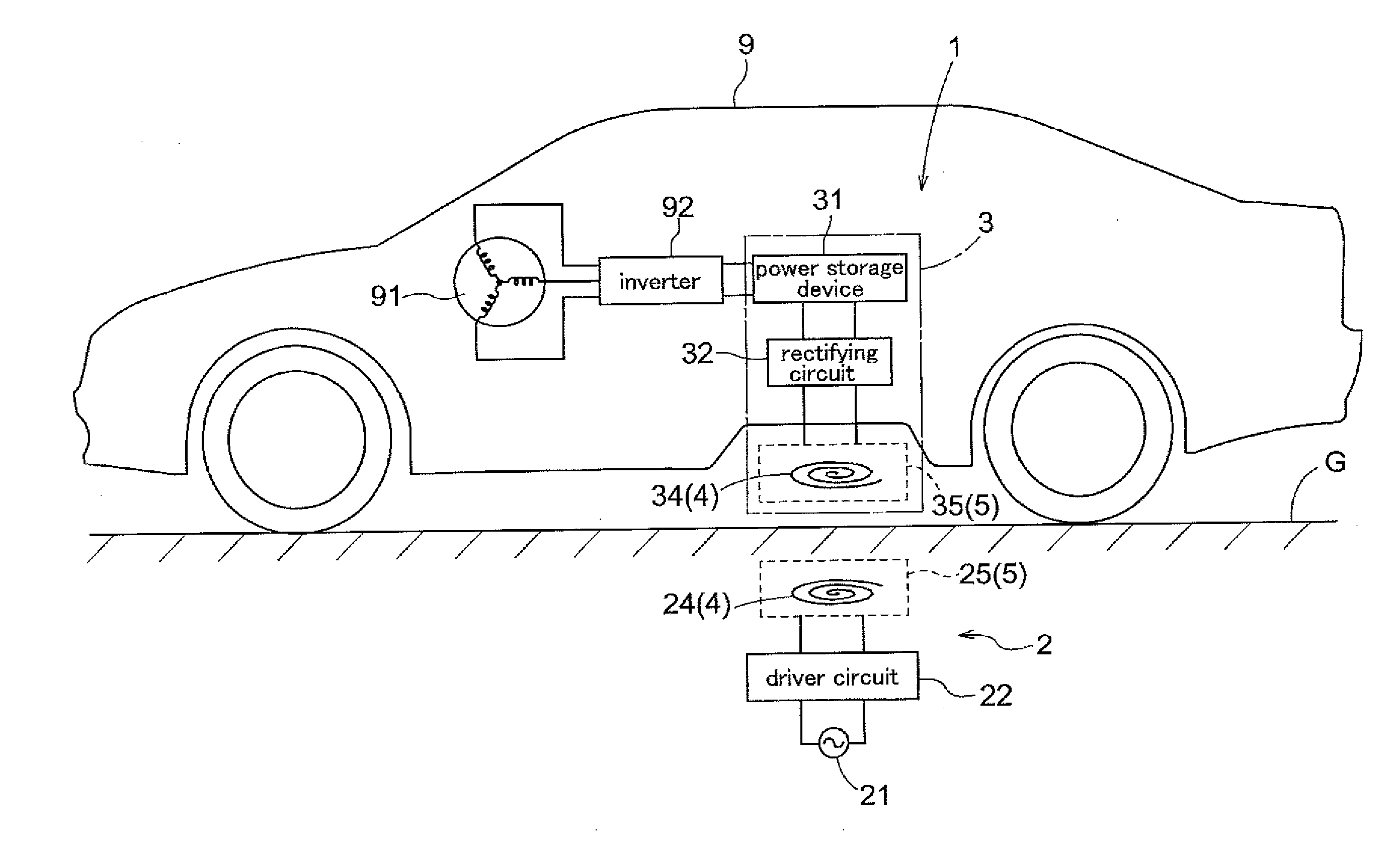
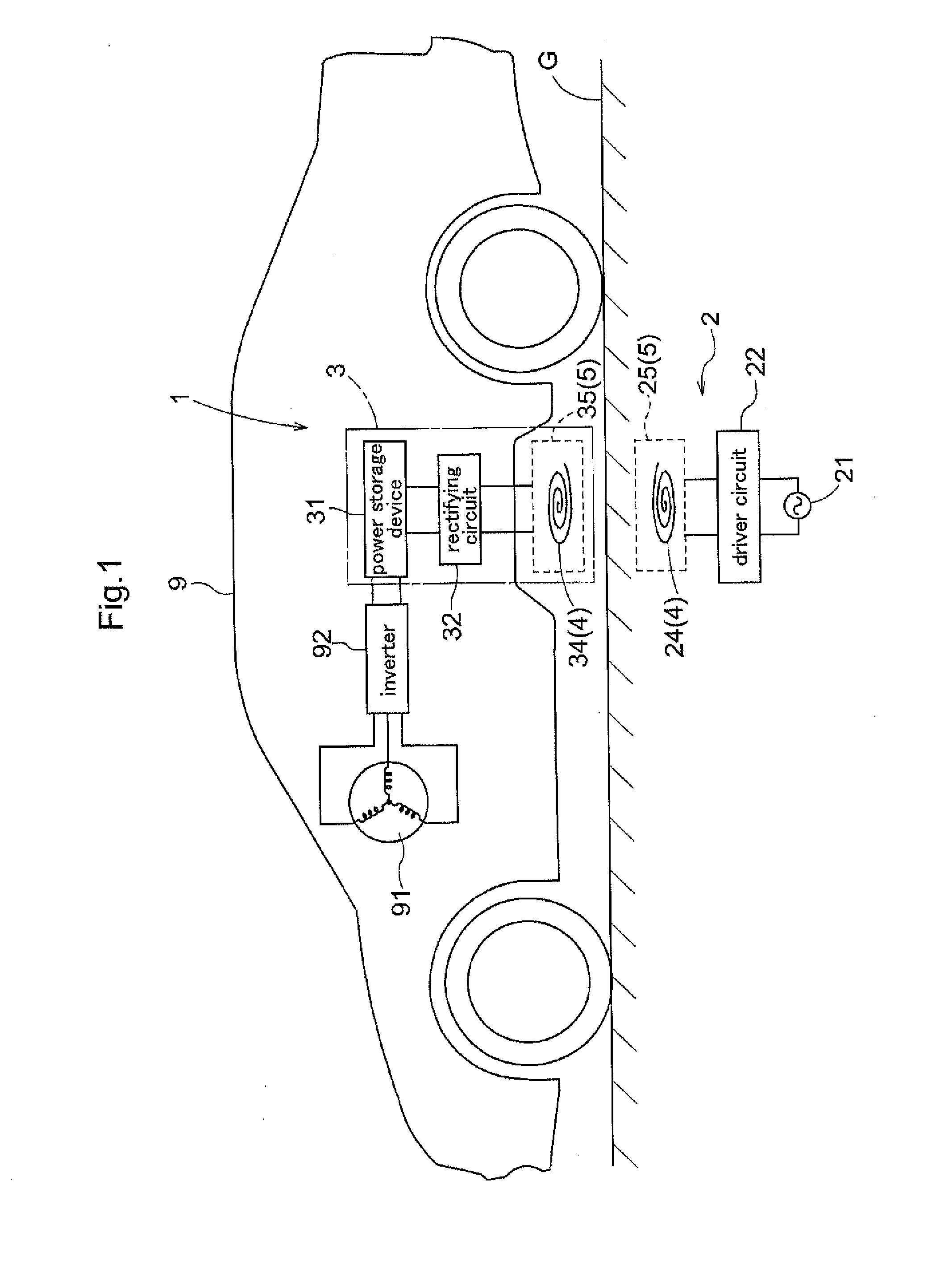
[0048]Next, embodiments of the present invention will be explained with reference to the accompanying drawings, taking a wireless power supply system for effecting wireless power supply to a vehicle, for example. As shown in FIG. 1, a wireless power supply system 1 (magnetic resonance power supply apparatus) is comprised of a power supplying system 2 installed at a power supply facility and a power receiving system 3 mounted on a vehicle 9. In the instant embodiment, the power supplying system 2 is installed near a ground surface G in the case of an outdoor facility or near a floor surface in the case of an indoor facility.

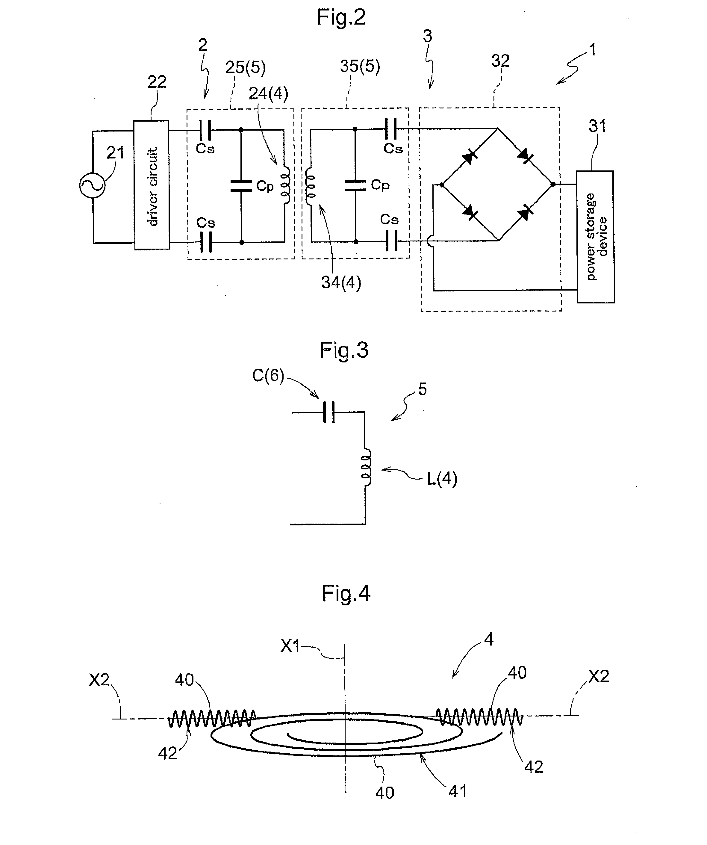
[0049]As shown in FIG. 1 and FIG. 2, the power supplying system 2 includes an AC power source 21, a driver circuit 22 and a power supplying side resonance circuit 25. The power supplying side resonance circuit 25 includes a power supplying side resonance coil 24. The power receiving system 3 includes a power receiving side resonance circuit 35, a rectifying circui...

second embodiment

[0095]In the first embodiment described above, there was shown an example wherein the first reference axis X1 of the main coil portion 41 and the second reference axis X2 of the auxiliary coil portion 42 has an intersecting relationship. That is, in the first embodiment, there was explained an arrangement wherein the auxiliary coil portion 42 is provided to be able to adjust the directivity in the direction along the first reference axis X1 of the main coil portion 41. However, such adjustable directivity is not limited to the direction along the first reference axis X1, but can be a direction intersecting this first reference axis X1. Next, such configuration will be described as the second embodiment. Incidentally, regarding those portions overlapped with the first embodiment, explanation thereof will be omitted when appropriate.

[0096]FIG. 22 schematically shows one example of the substrate 70 (core member 7) used for forming the main coil portion 41 and the auxiliary coil portion...


PUM

PropertyMeasurementUnit
resonant frequencyaaaaaaaaaa
angleaaaaaaaaaa

Abstract

Provided is an antenna coil capable of forming a magnetic field in a desired direction in an efficient manner, while suppressing leakage of magnetic flux into a space other than the space in which the magnetic field is formed. The antenna coil includes a main coil portion formed by winding a length of conductor wire around a first reference axis and an auxiliary coil portion formed by winding the conductor wire around a second reference axis. The second reference axis is set to intersect the magnetic flux of the main coil portion at an axial end of the auxiliary coil portion. The main coil portion and the auxiliary coil portion are connected to together form a closed circuit.

Description

TECHNICAL FIELD[0001]The present invention relates to an antenna coil for use in wireless transmission.BACKGROUND ART[0002]In recent years, there has been a growing interest in a technique of supplying electric power in a wireless manner without using a cable, that is, in a contactless manner, to an electric instrument or an electric device movable without being fixedly positioned, such as a mobile phone, a personal digital assistance (PDA), an electrically assisted bicycle, an electric vehicle, a hybrid automobile, etc. For instance, Japanese Unexamined Patent Application Publication No. 2011-234496 (Patent Document 1) discloses a technique for contactless power supply to a vehicle from a power source disposed outside the vehicle. Also, Japanese Unexamined Patent Application Publication No. 2008-244575 (Patent Document 2) discloses a technique relating to an antenna coil for short-distance wireless communication.[0003]In this way, in a coil unit including a resonance coil (antenna ...

Claims


Application Information

Patent Timeline
Patent Type & Authority Applications(United States)
IPC IPC(8): H01F38/14H02J17/00H01Q7/00H01Q7/08H01Q19/00
CPCH01F38/14H02J17/00H01Q7/00H01Q7/08Y02T90/12Y02T10/7072B60L53/38Y02T10/70H02J50/12H02J50/70Y02T90/14H02J50/23
Inventor YAMAKAWA, HIROYUKISATOU, KENICHIROU
Owner EQUOS RES
Why Eureka
Try Eureka