Assembled battery

a battery and assembly technology, applied in the field of assembled batteries, can solve the problems of increasing assembling and working costs, increasing the cost of power sources, increasing the weight, etc., and achieve the effects of reducing the degree of damage, reducing the risk of short circuit due to erroneous wiring, and improving working efficiency

Active Publication Date: 2007-06-14
HITACHI VEHICLE ENERGY
View PDF3 Cites 50 Cited by
  • Summary
  • Abstract
  • Description
  • Claims
  • Application Information

AI Technical Summary

Benefits of technology

[0016] When such a constitution is employed that each of the terminal bus bars fixed to the inner frame has a male screw portion or a female screw portion, electrical connection of a plurality of the assembled batteries can be performed by only screw-fastening inter-assembled battery bus bars for electrically connecting the assembled battery to the male screw or the female screw, and required power can be obtained by simply increasing or decreasing the number of assembled batteries to be connected. When such a constitution is employed that a hole or a notched groove for positioning or fixing is formed in the first and second outer frames, positioning of the assembled batteries can be performed by only fitting the holes or the notched grooves to protrusions provided on a platform for fixing the assembled batteries so that working efficiency is improved. Since vibration-proof performance is imparted to the assembled battery or collected assembled battery obtained by arranging a plurality of the assembled batteries, performance suitable for a power source for a mobile machine can be developed. Further, even if any defect occurs in one unit cell in the collected assembled battery, only an assembled battery to which the defective unit cell belongs can be replaced by a new assembled battery, so that a degree of damage can be reduced from the whole collected assembled battery to an individual assembled battery. When such a constitution is employed that each of the lead wires for voltage detection is fixed with a connector at one side thereof, each of the lead wires for voltage detection connected to each unit cell are collected by the connector, so that wire connection in the collected assembled battery is facilitated and short-circuit due to erroneous wiring or the like can be prevented from occurring.

Problems solved by technology

A work for serially connecting the several tens unit cells through the above-described conductive members requires a large number of steps, which results in high cost power source from a viewpoint of prevention of short-circuiting.
However, when any defect occurs in one of the connected unit cells, all the several tens unit cells connected are wholly handled as a defective product.
However, since the number of parts to be fastened increases in this connection state, such a problem as increase in part cost, increase in assembling and working cost, or increase in weight arises.
When the unit cell is a lithium ion cell, a lead line for detecting a voltage of each unit cell to monitor the same must be connected to the unit cell and work for the connection is much cumbersome.
Therefore, a space occurring between parts is largely influenced by vibrations, which may cause such a problem as stoppage of power supplying due to breaking at a connection portion or an insulated portion, or heat generation or firing due to short-circuiting.
The frame for holding and fixing several tens unit cells collectively has a complicated shape, causes increase in cost, and requires complicated assembling work thereof, so that cost required for the work increases.
Further, in a recycling work for the assembled battery obtained by collectively fixing respective unit cells, such a problem occurs that a disassembling work becomes more complicated than the assembling work.

Method used


Image

  • Assembled battery
  • Assembled battery
  • Assembled battery

Examples


Embodiment Construction

[0024] With reference to the drawings, an embodiment that the present invention is applied to a battery module (collected assembled battery) for an electric vehicle will be explained below.

[0025] (Constitution)

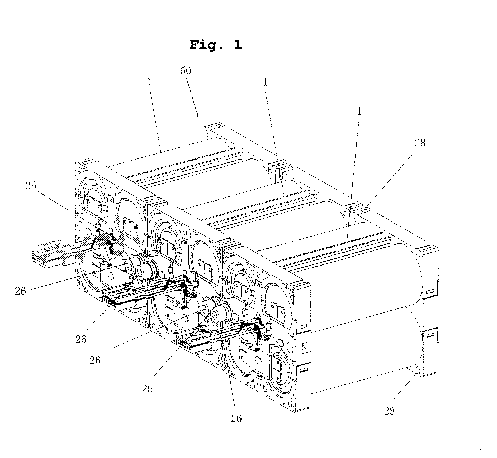
[0026] As shown in FIG. 1, a battery module 50 according to the embodiment is equipped with three assembled batteries 1 which are connected in series.

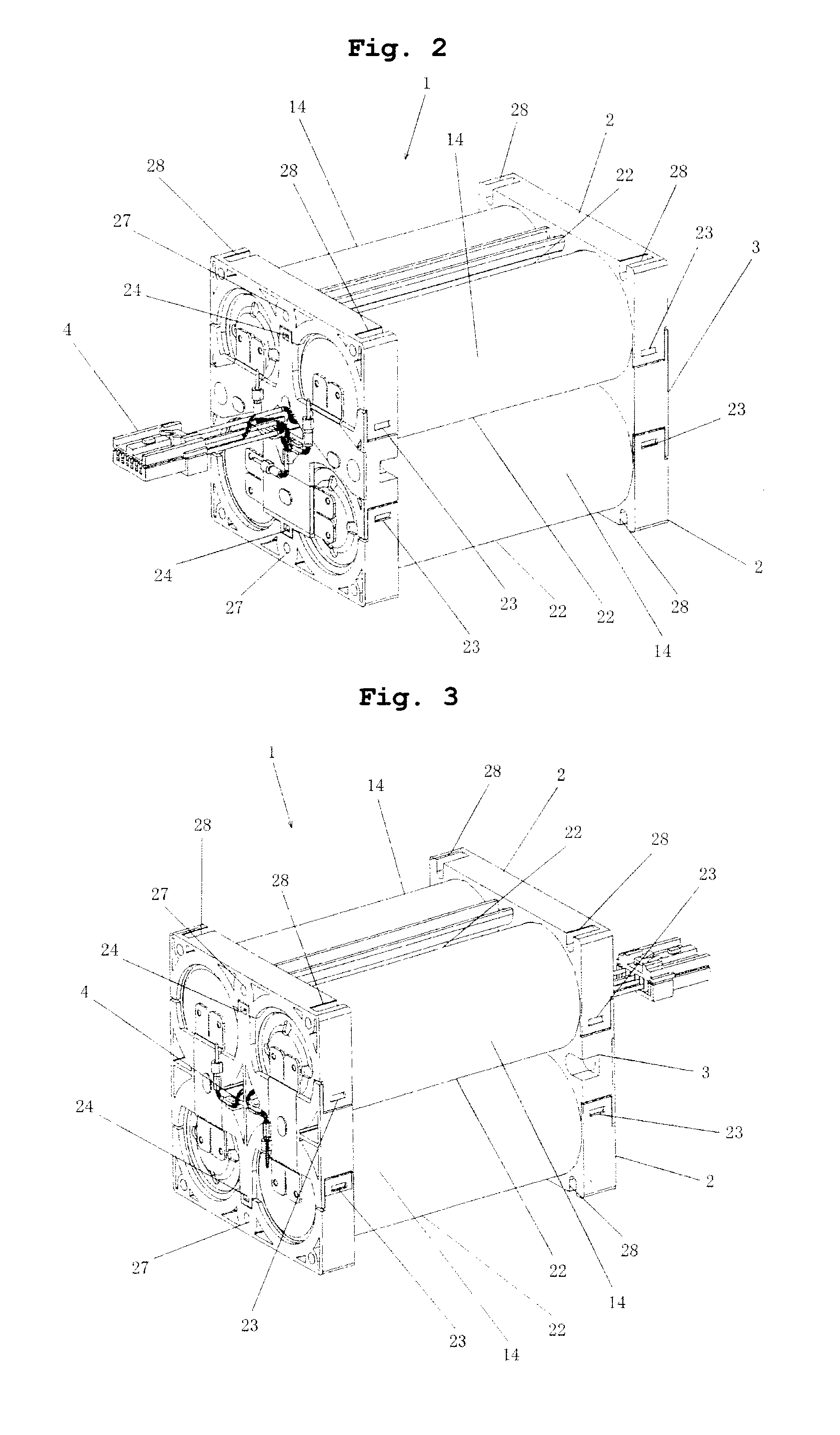
[0027] As shown in FIGS. 2 and 3, the assembled battery 1 has four cylindrical lithium-ion batteries 14 (hereinafter, called “unit cells 14”), a frame that retains the unit cells 14, connecting members (bus bars) that connect the unit cells 14, and lead wires for voltage detection for detecting voltages of the unit cells 14.

[0028] Each unit cell 14 has a winding group obtained by winding a positive electrode and a negative electrode though a separator in a cylindrical metal container having a bottom, where the electrode group is infiltrated into non-aqueous electrolytic solution. As shown in FIGS. 6 and 7, an upper portion of...


PUM

PropertyMeasurementUnit
rated voltageaaaaaaaaaa
voltageaaaaaaaaaa

Abstract

The present invention provides an assembled battery with reduced weight and high reliability that can achieve improvement of assembling easiness at low cost. An assembled battery is provided with a frame holding a plurality of unit cells 14 having positive polarity at one end and negative polarity at the other end. The frame is composed of two outer frames 2 having the same shape and an inner frame 3. The unit cells 14 constituting an assembled battery 1 are disposed on both sides of the inner frame 3, and one outer frame 2 and the other outer frame 2 are disposed such that the unit cells are sandwiched between the former outer frame 2 and the inner frame 3 and between the latter outer frame 2 and the inner frame 3. The two outer frames 2 are joined to the inner frame 3 through side face coupling portions 23 and vertical coupling portions 24. The inner frame 3 is fixed with positive electrode bus bars 5, negative electrode bus bars 6, and inter-unit cell bus bars 7 for electrically connecting the unit cells 14 in series, and lead wires for voltage detection with a connector 4 for detecting voltages of the unit cells 14.

Description

FIELD OF THE INVENTION [0001] The present invention relates to an assembled battery, and in particular to an assembled battery provided with a frame holding a plurality of unit cells, each unit cell having a positive electrode at one end and a negative electrode at the other end. DESCRIPTION OF THE RELATED ART [0002] Conventionally, in an assembled battery (a collected cells), high voltage or large capacity is achieved by electrically connecting a plurality of secondary batteries (unit cells) in series or in parallel. In order to assemble a plurality of unit cells, a method for welding terminals of unit cells to bus bars made of a conductive member to connect unit cells in series and / or in parallel or a method for providing preliminarily worked screw portions on positive electrode terminals and negative electrode terminals of unit cells or joining conductive members having worked screw portions to positive and negative electrode terminals and then fastening and fixing bus bars to th...

Claims


Application Information

Patent Timeline
Patent Type & Authority Applications(United States)
IPC IPC(8): H02J7/00H01M50/213H01M50/264H01M50/291H01M50/503H01M50/514H01M50/569
CPCH01M2/1016H01M2/105H01M2/1077H01M2/202H01M10/0525H01M10/48Y02T10/7011Y02E60/10H01M50/213H01M50/514H01M50/264H01M50/291H01M50/503H01M50/569
Inventor ONUKI, TOSHIAKIGOTO, TAKEYUKIIKEDA, KOUTAROUAIBA, TUNEMI
Owner HITACHI VEHICLE ENERGY
Why Eureka
Try Eureka