
Gaming machine

a technology of gaming machine and gaming machine body, applied in the field of gaming machine, to achieve the effect of ease of assembly and disassembly of the gaming machin

Active Publication Date: 2009-01-20
UNIVERSAL ENTERTAINMENT CORP
View PDF18 Cites 107 Cited by
  • Summary
  • Abstract
  • Description
  • Claims
  • Application Information

AI Technical Summary

Benefits of technology

[0008]It is an object of the invention to provide a gaming machine for facilitating work of attaching and detaching a liquid crystal display control board and reducing the number of steps.
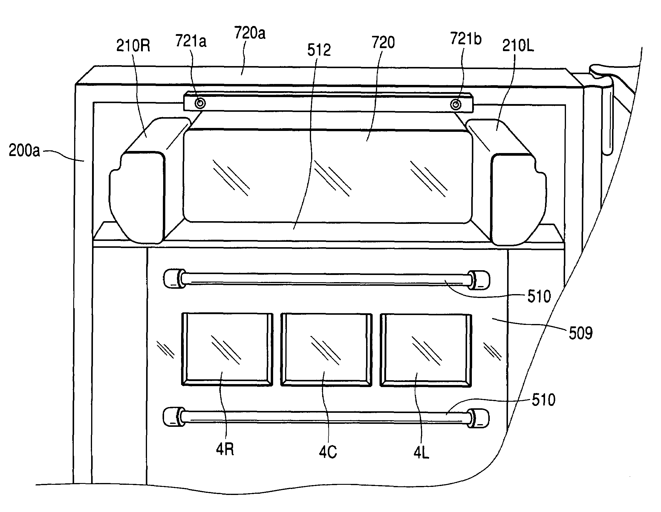
[0010]According to the configuration, the display control means is attached onto the cabinet and thus can be temporarily tacked to the cabinet using the attachment means and can be positioned. As the display control means is temporarily tacked, the attachment work of the display control means is facilitated and further the number of fixed parts can be reduced, so that the number of fixing steps can be decreased. Therefore, the assembling and disassembling work of the gaming machine is eased. Since detachment work is also easy to conduct, it is suited for recycling the display control means.
[0012]According to the configuration, the display control means can be temporarily tacked to the cabinet simply by inserting the hook into the hook hole. Thus, the display control means can be easily attached and detached as compared with the case where immediately the display control means is fixed to the cabinet. Therefore, the assembling and disassembling work of the gaming machine is eased. It is also suited for recycling the display control means.
[0014]According to the configuration, the display control means is disposed at the upper end of the cabinet and is hooked using the hook and the hook hole and further is fixed with a screw and the like, so that while the necessary number of steps is decreased, the display control means can be temporarily tacked and positioned before it is reliably fixed. Therefore, the assembling and disassembling work of the gaming machine is eased. It is also suited for maintaining and recycling the display control means.

Problems solved by technology

Therefore, there is a problem that when the liquid crystal display control board is attached or detached, the board needs to be positioned and attached while it is held.

Method used


Image

  • Gaming machine
  • Gaming machine
  • Gaming machine

Examples


first embodiment

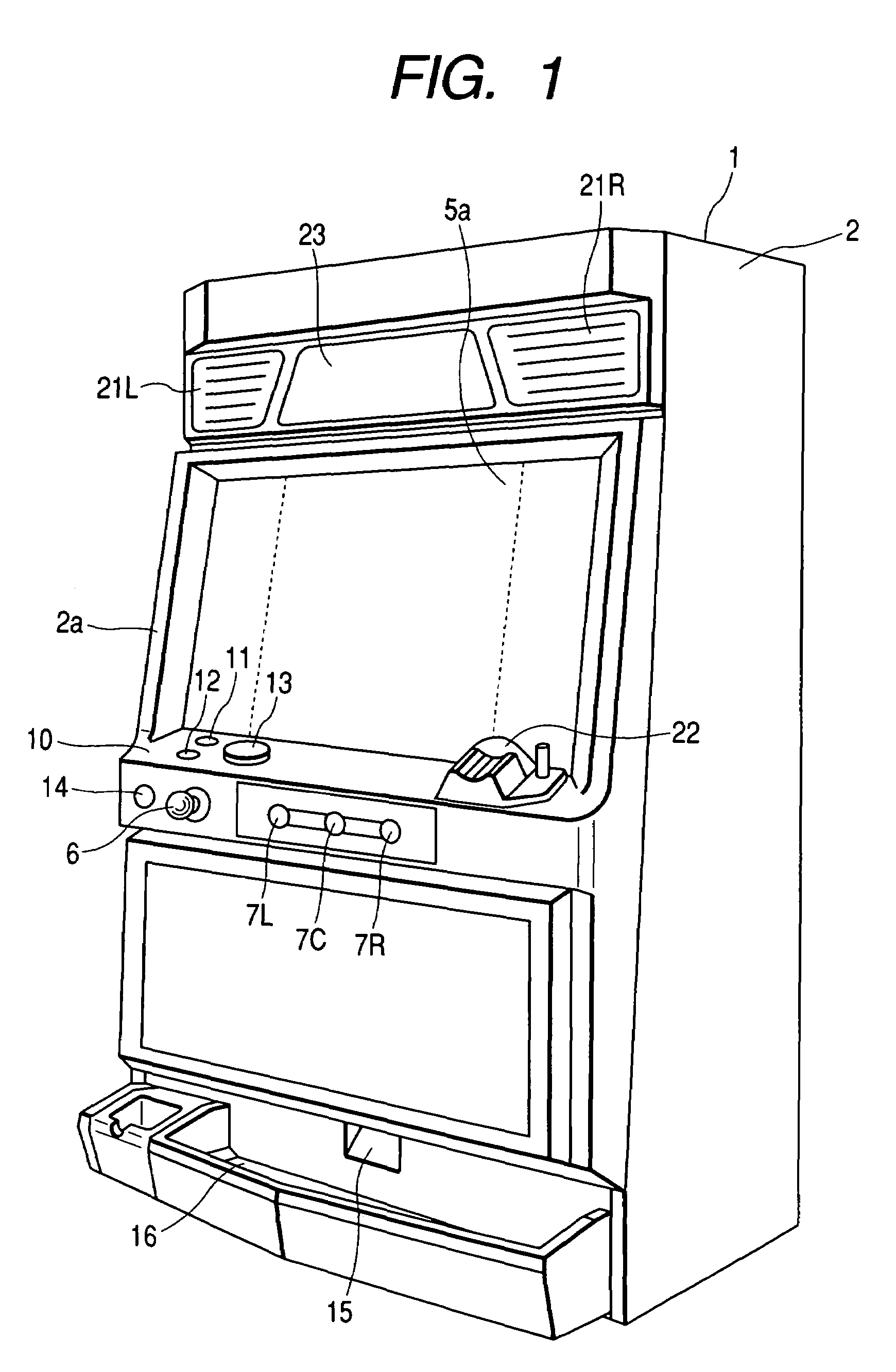
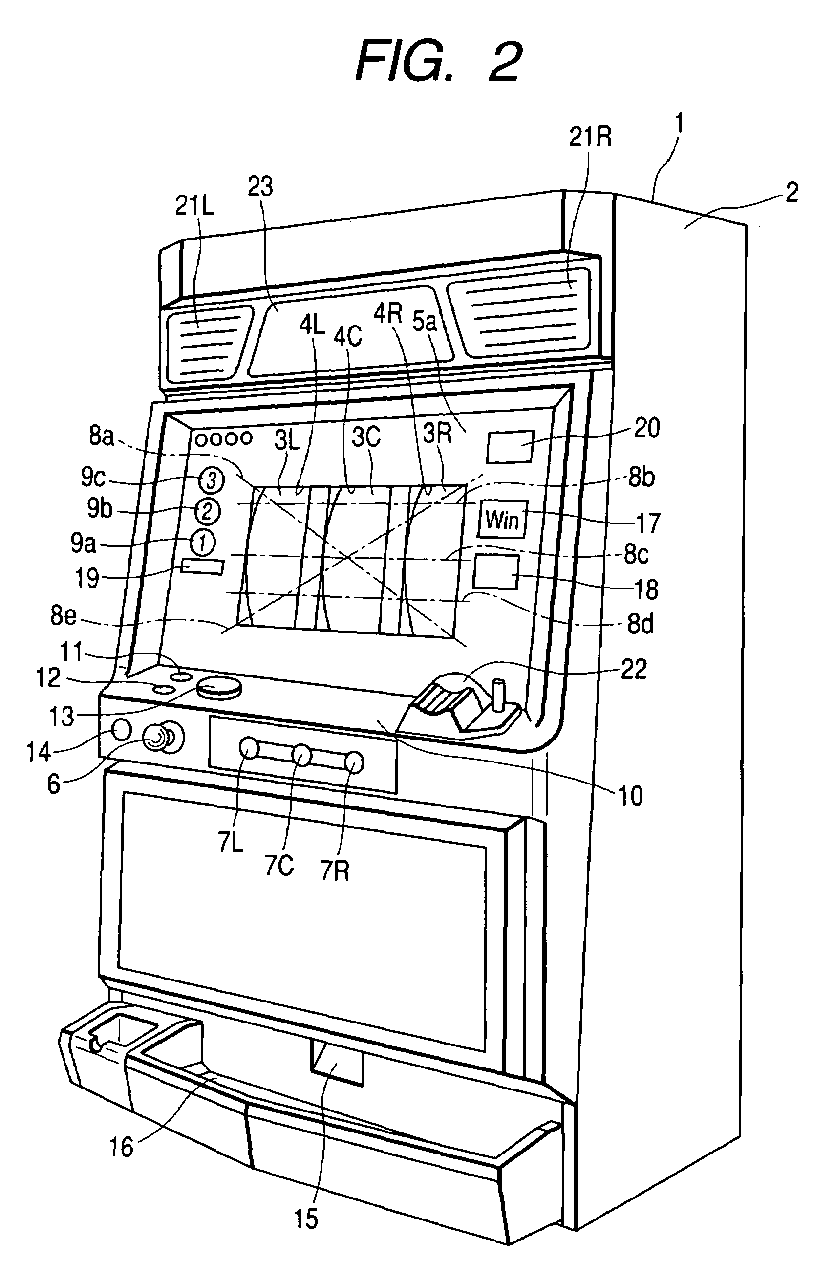
[0033]FIG. 1 shows a first embodiment applying a gaming machine according to the invention to a Pachi-Slot machine. In FIG. 1, BET lamps 9a, 9b, and 9c, a WIN lamp 17, a payout display unit 18, a credit display unit 19, and a bonus game information display unit 20 (described later) are not shown. FIG. 2 shows a state that a full screen display is not displayed by a liquid crystal display in a display screen 5a, and reels 3 placed at the back of the liquid crystal are displayed through the display screen 5a (liquid crystal display).

[0034]To being with, the configuration will be discussed. In FIGS. 1 and 2, a pinball slot machine 1 as a gaming machine is provided for the player to play a game using game medium such as a card storing information of the game play value given to the player as well as coins, medals, tokens, etc. In the description that follows, it is assumed that the player uses medals.

[0035]A panel display unit 2a roughly as a vertical plane is formed at the front of a c...

second embodiment

[0121]A pinball slot machine according to a second embodiment of the invention is almost the same as that according to the first embodiment except for attachment parts or attachment method of liquid crystal display control board 720a and therefore components identical with those previously described with reference to FIGS. 1 to 3 are denoted by the same reference numerals in FIGS. 14A and 14B and FIGS. 15A and 15B and will not be discussed again.

[0122]FIGS. 14A and 14B show the back of a liquid crystal display control board and a part of a cabinet to which the liquid crystal display control board is attached in the second embodiment of the invention.

[0123]In FIG. 14A, two attachment holes 725a and 725b each of a predetermined shape to attach projections 224a and 224b (described later) are made roughly horizontally in the attachment face of a cabinet section 200b (a part of cabinet) below the upper frame of a door 200a of a cabinet 200 of a pinball slot machine 1. On the other hand, ...

third embodiment

[0125]A pinball slot machine according to a third embodiment of the invention is almost the same as that according to the first embodiment except for attachment parts or attachment method of liquid crystal display control board 720a and therefore components identical with those previously described with reference to FIGS. 1 to 3 are denoted by the same reference numerals in FIG. 16 and will not be discussed again.

[0126]FIG. 16 shows a state in which a liquid crystal display control board is attached to a cabinet in the third embodiment of the invention.

[0127]In FIG. 16, a cabinet section 200b (a part of cabinet) lower than the upper frame of a door 200a of a cabinet 2 of a pinball slot machine 1 is formed with two hooks 223a and 223b upward and roughly horizontally as in the first embodiment. On the other hand, a liquid crystal display control board 720a to be attached to the cabinet section 200b is formed in lower positions of the back with two projections 724a and 724b each having...


PUM


Abstract

A pinball slot machine includes a board on which a main control circuit for determining an internal lottery of a game with a random number at a predetermined timing is placed, a liquid crystal display for displaying an effect image pertinent to the game, a liquid crystal display control board 720a, and hooks 223a and 223b and projections 724a and 724b having attachment holes for hooking the liquid crystal display control board 720a on a cabinet section 200b of the gaming machine. To attach the liquid crystal display control board 720a to the cabinet section 200b of the gaming machine, the hooks 223a and 223b are inserted into the attachment holes for temporarily tacking the liquid crystal display control board 720a. In this state, the liquid crystal display control board 720a is screwed at upper left and right ends into a door 200a.

Description

BACKGROUND OF THE INVENTION[0001]1. Field of the Invention[0002]The present invention relates to a gaming machine including a liquid crystal display.[0003]2. Description of the Related Art[0004]A recent slot machine including stop buttons (a so-called “pinball slot machine” or a so-called “Pachi-Slot machine” in Japan) has a mechanical variable display means provided with a plurality of rotation reels for variably displaying symbols in a front display window or an electric variable display means for displaying symbols on reels on a screen. As the player performs start operation, control means controls the variable display means for rotating the reels, thereby producing variable display of symbols. Then, the rotatable reels are stopped in order automatically in a given time or as the player performs stop operation. At this time, if the symbols on the reels appearing in the display window become a specific combination (winning symbol combination), game medium such as medals or coins a...

Claims


Application Information

Patent Timeline
IPC IPC(8): A63F13/00A63F9/24A63F5/04G07F17/32
CPCG07F17/32
Inventor EMORI, KAZUKI
Owner UNIVERSAL ENTERTAINMENT CORP
Learn More