Electrically operated vibrating drill/driver

a technology of electric operation and vibrating drill, which is applied in the direction of portable power-driven tools, portable drilling machines, manufacturing tools, etc., can solve the problems of unstable drilling work, work a clutch mechanism, etc., and achieve the effect of finely varying the working torque and working drilling more stabl

Inactive Publication Date: 2005-05-17
MATSUSHITA ELECTRIC WORKS LTD
View PDF12 Cites 110 Cited by
  • Summary
  • Abstract
  • Description
  • Claims
  • Application Information

AI Technical Summary

Benefits of technology

[0009]Preferably, the switching ring has a projecting portion formed therewith between the recessed portion and a place where the tip of the switching plate engages in the recessed portion during the drilling mode. As the switching ring and the switching handle is further prevented from rotating during the operation thereof under the drilling mode, it is possible to work drilling more stable without working the clutch mechanism fail to switch over to the clutch mode.
[0010]Yet preferably another switching plate having a tip formed therewith is further furnished, and the switching ring has another recessed portion defined therein for engagement with the another switching plate, and a distance between the longitudinal axis of the spindle and a position at which the tip of the switching plate engages in the recessed portion differs from a distance between the longitudinal axis of the spindle and a position at which the tip of the another switching plate engages in the another recessed portion. The switching handle can thus rotate an angle of about 360 degrees for switching over from the clutch mode to the drilling mode, making it possible to vary the working torque finely.

Problems solved by technology

In the traditional vibrating drill / driver constructed to selectively operate under the clutch mode, the drilling mode and the vibrating mode in this order, unexpected external shock in working in the drilling mode makes the switching handle rotate and causes to work a clutch mechanism.
In addition, in the event such an operation occurs against the will of the user of the vibrating drill / driver, the stable drilling work can no longer be performed smoothly.

Method used


Image

  • Electrically operated vibrating drill/driver
  • Electrically operated vibrating drill/driver
  • Electrically operated vibrating drill/driver

Examples


Embodiment Construction

[0034]This application is based on applications Nos. 2002-246719 and 2002-247820, both filed Aug. 27, 2002 in Japan, the respective contents of which are hereby incorporated by reference.

[0035]Now, description will be given below in detail of an embodiment of a vibrating drill / driver according to the present invention, referring to the accompanying drawings.

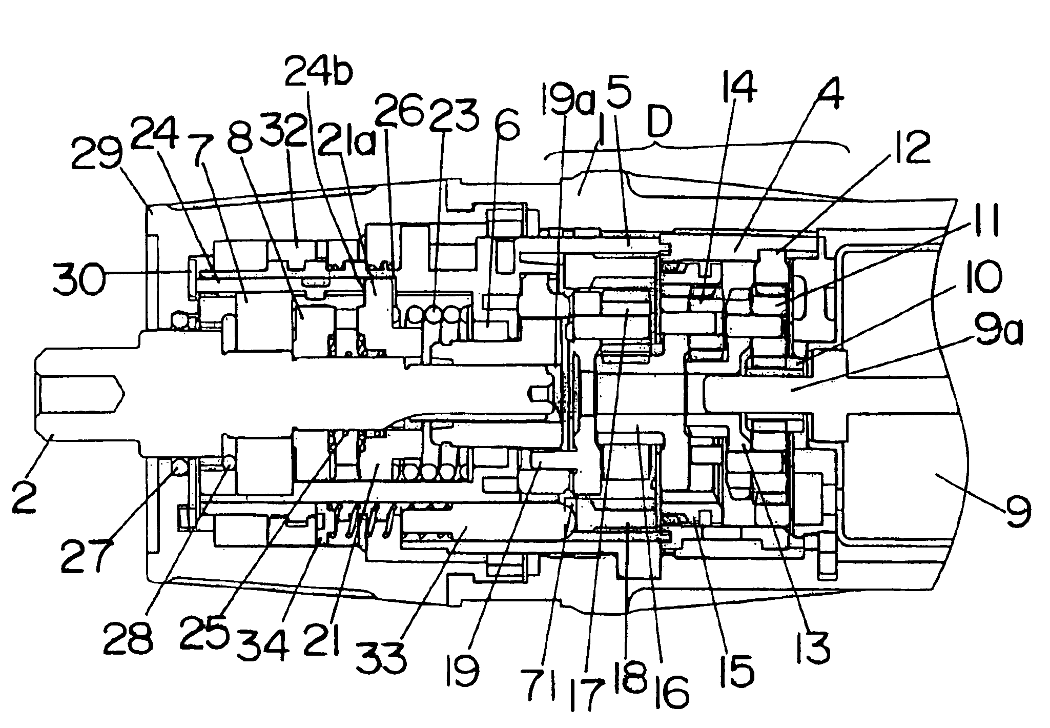
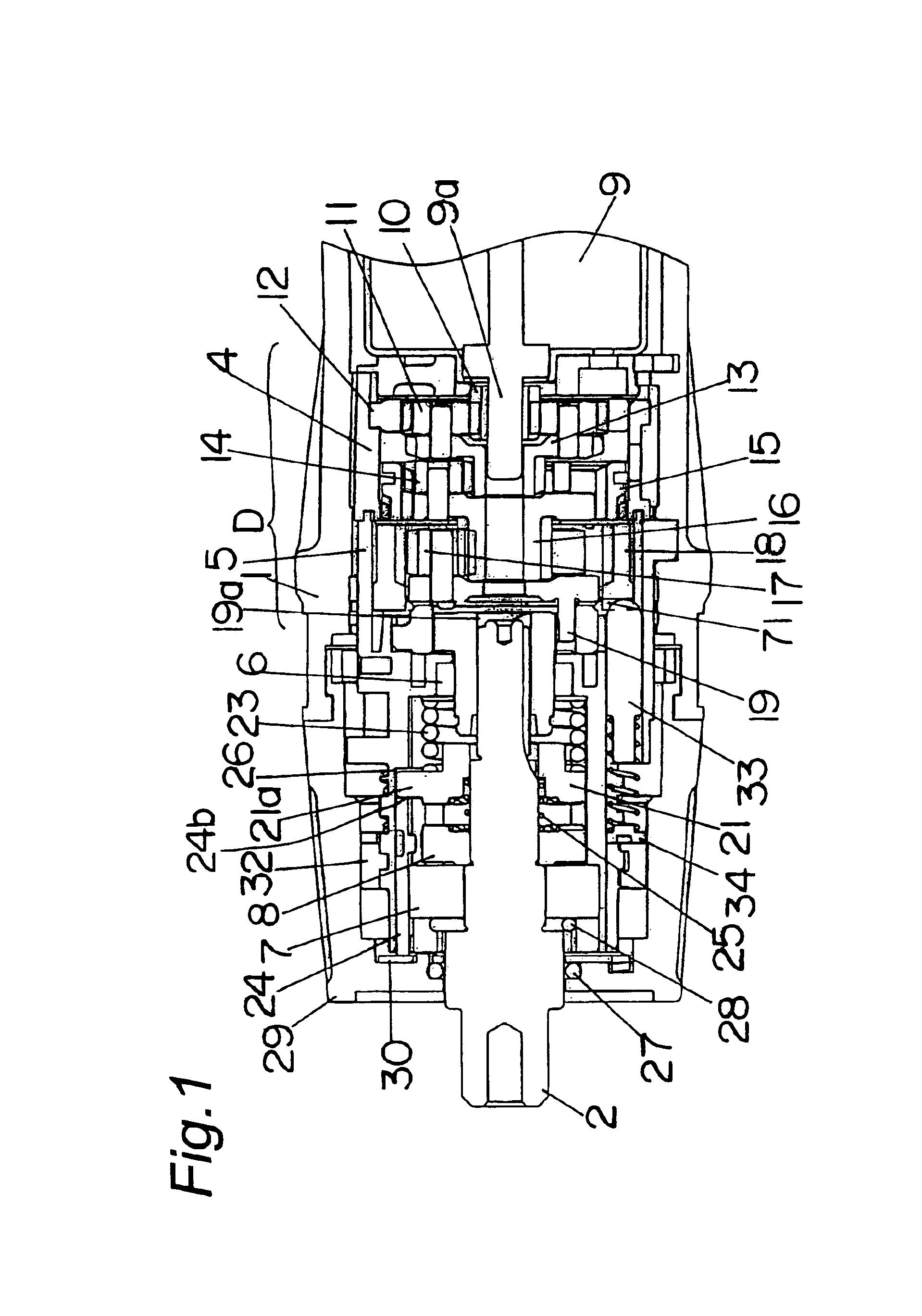
[0036]FIG. 1 shows a portion of a vibrating drill / driver set under a clutch mode. A free end of a spindle 2, which projects axially outwardly from a front end surface of a tool housing 1 that defines an outer shell of the vibrating drill / driver, is designed to receive a chuck (not illustrated) for replaceably supporting a bit which may be a drill bit or a screwdriver bit. The spindle 2 is supported by a gear box 4 and a casing 5, both disposed within the tool housing 1, through spindle bearings 6 and 7, so as to rotate freely about the longitudinal axis thereof and also as to slide freely in an axial direction thereof. For this p...


PUM

PropertyMeasurementUnit
angleaaaaaaaaaa
angleaaaaaaaaaa
angle of rotationaaaaaaaaaa

Abstract

A vibrating drill / driver includes a motor for driving a spindle about the longitudinal axis thereof, a switching handle supported for rotation about a longitudinal axis thereof, a clutch mechanism for varying a working torque in dependence on rotation of the switching handle, a switching ring having a recess and capable of rotating together with the switching handle, and a switching plate having a tip for engagement in the recess. A vibrating cam mechanism is provided to be operable to undergo a slidable engagement to provide a vibration for the spindle in an axial direction thereof when the tip of the switching plate is engaged in the recess of the switching ring. With the above-described construction, the rotation of the switching handle in one direction causes the vibrating drill / driver to be set in one of a clutch mode, a vibrating mode, and a drilling mode in this order.

Description

TECHNICAL FIELD OF THE INVENTION[0001]The present invention relates to a hand-held vibrating drill / driver capable of being operated under one of a plurality of operating modes, i.e., a clutch mode, a drilling mode and a vibrating mode one at a time.DESCRIPTION OF THE RELATED ART[0002]A vibrating drill / driver is an electric combination tool (i.e., an electrically operated combination drill and driver) that can be used one at a time as a power screwdriver with a driver bit attached to the chuck, and as a power drill with a drilling bit attached to the chuck for boring holes by a rotating abrasion. As a variant of this electric combination tool, there is known a vibrating drill / driver having a switching handle with which the tool can be set in one of a clutch mode under which the working torque can be adjusted, a drilling mode and a vibrating mode. A number of the vibrating drill / drivers have hitherto been proposed and are constructed to provide a varying working torque in multistages ...

Claims


Application Information

Patent Timeline
Patent Type & Authority Patents(United States)
IPC IPC(8): B23Q5/00B25F5/00B25D16/00B23B45/16
CPCB25D16/003B25D16/006B25D11/102B25D2216/0038B25D2250/165B25D2216/0023
Inventor TOYAMA, KAZUTOYAMAMOTO, MASAO
Owner MATSUSHITA ELECTRIC WORKS LTD
Why Eureka
Try Eureka