Cyclonic separation apparatus

a technology of cyclonic separation and cyclone, which is applied in the direction of dispersed particle separation, cleaning equipment, separation processes, etc., can solve the problems of clogging the bag filter, affecting and small risk of dust and dirt passing, so as to improve the performance of vacuum cleaners and prevent clogging. , the effect of convenient maintenan

Inactive Publication Date: 2013-04-18
BLACK & DECKER INC
View PDF2 Cites 105 Cited by
  • Summary
  • Abstract
  • Description
  • Claims
  • Application Information

AI Technical Summary

Benefits of technology

[0022]It is an object of the present invention to provide an improved cyclonic separation apparatus which is convenient to maintain in good working order. It is also an object of the present invention to provide a motor, fan and cyclonic separation apparatus arrangement particularly suitable for use in a vacuum cleaner due to its ease of maintenance. A further object of the invention is to provide a vacuum cleaner comprising such a motor, fan and cyclonic separation apparatus arrangement.

Problems solved by technology

There is always a small risk of dust and dirt passing through the bag filter and it is undesirable that it be allowed to pass through the fan and cause damage.
This progressively clogs the bag filter.
Hence, the bag filter needs replacement before it becomes too full and before vacuum cleaner performance becomes unacceptable.
The volume of the collection chamber must be sufficiently large to merit the cost of regular bag filter replacement.
Filtered material accumulates around, and progressively clogs, the filter.
Over time and use, dirt may accumulate in corners of these ducts, and around other internal components, like, for example, filters, grilles, cyclone nozzles etc.

Method used


Image

  • Cyclonic separation apparatus
  • Cyclonic separation apparatus
  • Cyclonic separation apparatus

Examples


first embodiment

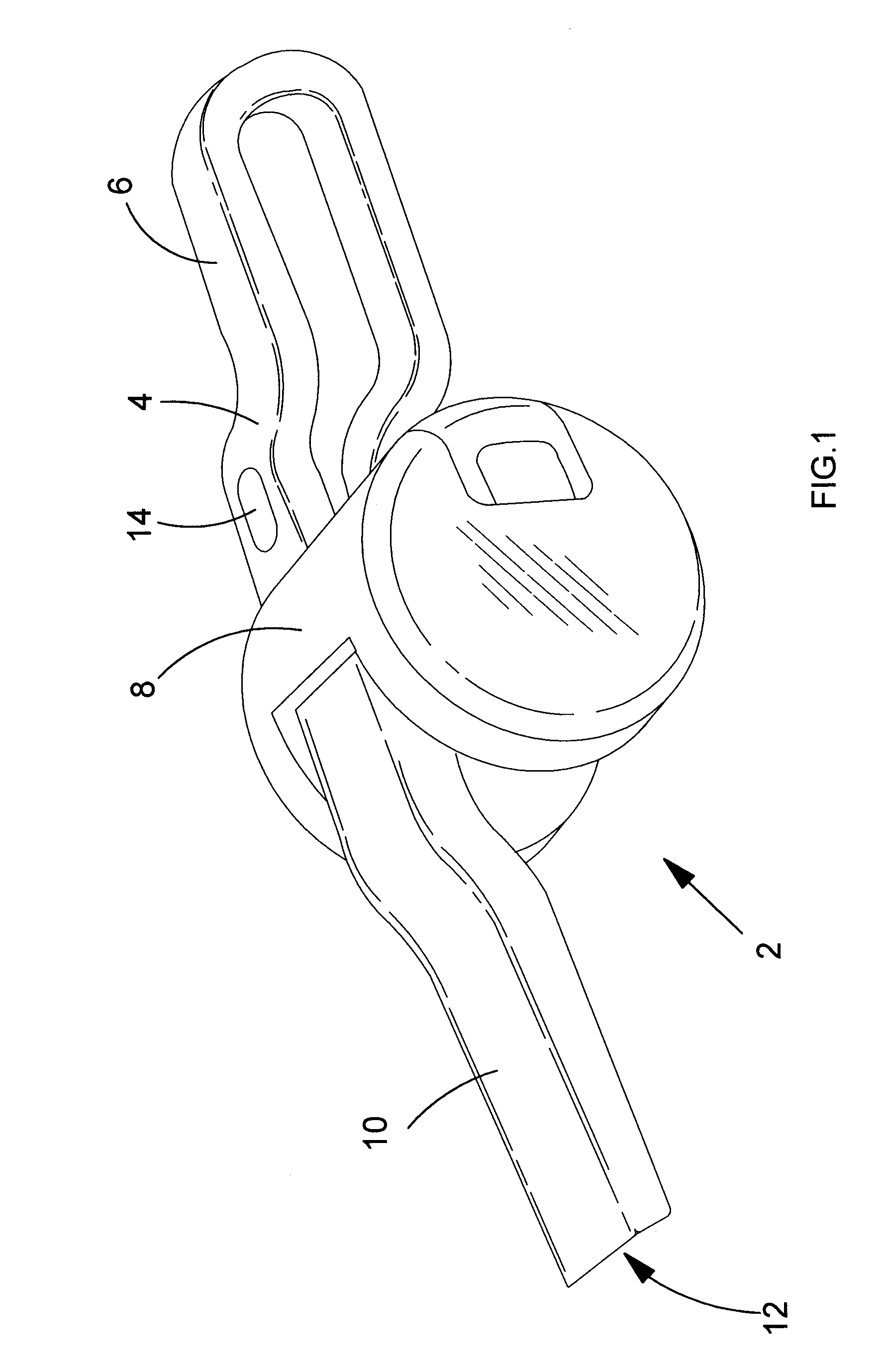
[0081]Referring to FIG. 1, there is shown first embodiment of a hand-held vacuum cleaner 2 comprising a main body 4, a handle 6 connected to the main body, a cyclonic separation apparatus 8 mounted transverse across the main body, and a dirty air duct 10 with a dirty air inlet 12 at one end. The vacuum cleaner comprises a motor coupled to a fan for generating air flow through the vacuum cleaner and rechargeable cells (not shown) to energise the motor when electrically coupled by an on / off switch 14.

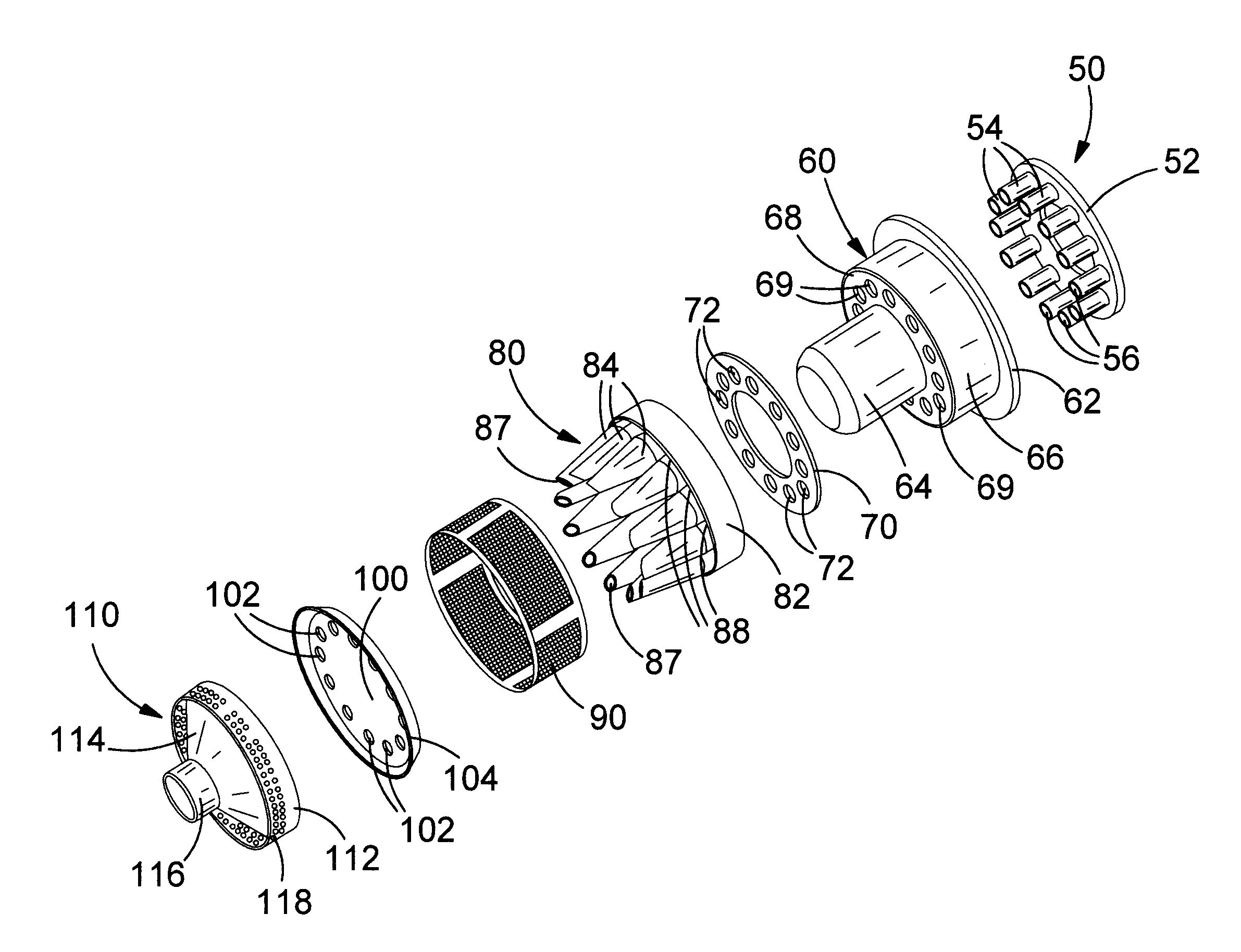
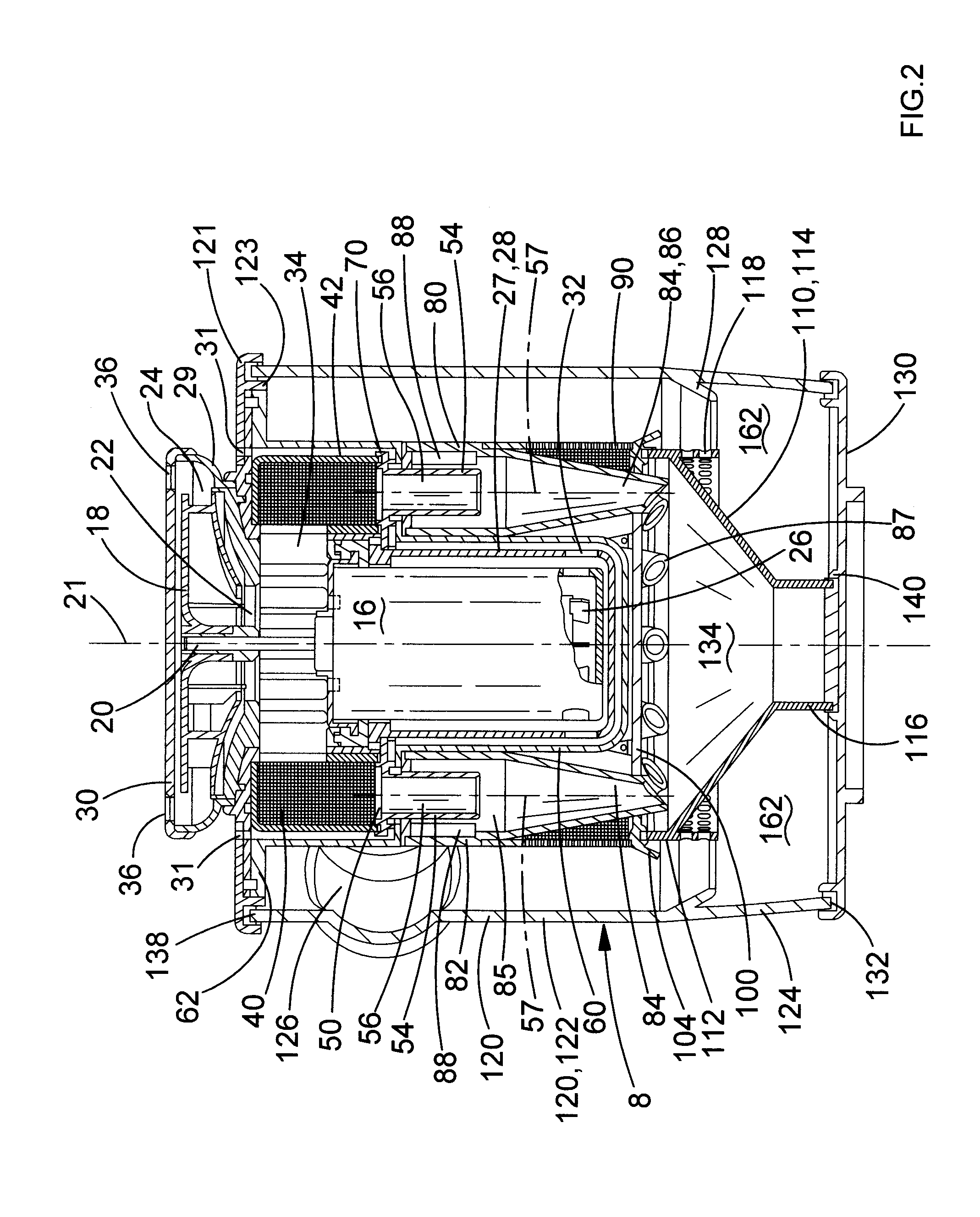
[0082]Referring to FIGS. 2 to 8, there is shown an arrangement comprising the motor 16, the fan 18 and the cyclonic separation apparatus 8. The motor has a drive shaft 20 with a central axis 21. The fan is a centrifugal fan 18 with an axial input 22 facing the motor and a tangential output 24. The fan has a diameter of 68 mm. The fan is mounted upon the drive shaft at the top of the motor. In use, the motor drives the fan to generate air flow through the cyclonic separation apparatus, as ...

second embodiment

[0119]Referring to FIGS. 10 and 11, there is shown a hand-held vacuum cleaner 202 comprising a main body 204 with a main axis 205, a handle 206, a cyclonic separation apparatus 208 mounted transverse to the main axis of the main body, and a dirty air duct 210 with a dirty air inlet 212 at one end. The vacuum cleaner comprises a motor 216 coupled to a fan for generating air flow through the vacuum cleaner and rechargeable cells 217 to energise the motor when electrically coupled by an on / off switch 214.

[0120]Referring to FIGS. 12 to 16, there is shown an arrangement comprising the motor 216, the rechargeable cells 217, the fan 218, a pre-fan filter 240, a cyclonic separation apparatus outlet duct 260 and the cyclonic separation apparatus 208.

[0121]The motor has a drive shaft 220 with a longitudinal central axis 221. The fan is a centrifugal fan 218 with an axial input 222 facing away from the motor and a tangential output 224. The fan has a diameter of 68 mm. The fan is mounted upon ...

third embodiment

[0156]Referring to FIG. 23, there is shown hand-held vacuum cleaner 402 comprising a main body 404 with a handle 406, a cyclonic separation apparatus 408 mounted to the main body, and a dirty air duct 410 with a dirty air inlet 412 at one end. The vacuum cleaner comprises a motor coupled to a fan for generating air flow through the vacuum cleaner and rechargeable cells to energise the motor when electrically coupled by an on / off switch 414.

[0157]Referring to FIGS. 24 to 27, there is shown in more detail the motor 416, the rechargeable cells 417, the fan 418, a pre-fan filter 440, a cyclonic separation apparatus outlet duct 460 and the cyclonic separation apparatus 408.

[0158]The motor has a drive shaft 420. The fan 418 is mounted upon the drive shaft at the top of the motor. The fan has a diameter of approximately 68 mm. The cells 417 are arranged about the motor 416. In use, the motor drives the fan to generate air flow through the cyclonic separation apparatus, as will be described...


PUM

PropertyMeasurementUnit
diameteraaaaaaaaaa
diameteraaaaaaaaaa
diameteraaaaaaaaaa

Abstract

A cyclonic separation apparatus for a vacuum cleaner, the cyclonic separation apparatus comprising: a first cyclonic separating unit comprising a hollow substantially cylindrical dirt container with a central axis, an air inlet port arranged tangentially through a side wall of the dirt container and an air outlet; and a second cyclonic separating unit comprising at least one cyclone with an air inlet port and an air outlet port, wherein the second cyclonic separating unit receives air flow downstream from the first cyclonic separating unit, wherein the second cyclonic separating unit is located within the dirt container and wherein the second cyclonic separating unit is detachably connected to the dirt container for removal through either longitudinal end of the dirt container. A vacuum cleaner comprising a motor coupled to a fan and the cyclonic separation apparatus.

Description

CROSS-REFERENCE TO RELATED APPLICATIONS[0001]This application claims priority to EP Patent Application No. EP 11 184 801.6 filed Oct. 12, 2011, the contents thereof to be incorporated herein by reference in its entirety.FIELD OF THE INVENTION[0002]The present invention relates to a cyclonic separation apparatus. In particular, but not exclusively, the present invention relates to a cyclonic separation apparatus for use in vacuum cleaners.BACKGROUND OF THE INVENTION[0003]Vacuum cleaners are well known for collecting dust and dirt, although wet-and-dry variants which can also collect liquids are known as well. Typically, vacuum cleaners are intended for use in a domestic environment, although they also find uses in other environments, such as worksites or in the garden. Generally, they are electrically powered and therefore comprise an electric motor and a fan connected to an output shaft of the motor, an inlet for dirty air, an outlet for clean air and a collection chamber for dust, ...

Claims


Application Information

Patent Timeline
Patent Type & Authority Applications(United States)
IPC IPC(8): B01D45/16
CPCA47L9/1691A47L9/1633
Inventor SMITH, KEVIN
Owner BLACK & DECKER INC
Why Eureka
Try Eureka