Sound system with dedicated vocal channel

a vocal channel and sound system technology, applied in the field of karaoke, public address and audio systems, can solve the problems of lack of definition of vocals, lack of direction, muddy sound, etc., and achieve the effect of clean and vibrant sound

a vocal channel and sound system technology, applied in the field of karaoke, public address and audio systems, can solve the problems of lack of definition of vocals, lack of direction, muddy sound, etc., and achieve the effect of clean and vibrant sound

US20050239030A1Inactive Publication Date: 2005-10-27MICA ELECTRONICS CORP A CALIFORNIA CORP

Image

  • Sound system with dedicated vocal channel
  • Sound system with dedicated vocal channel
  • Sound system with dedicated vocal channel

Examples


Embodiment Construction

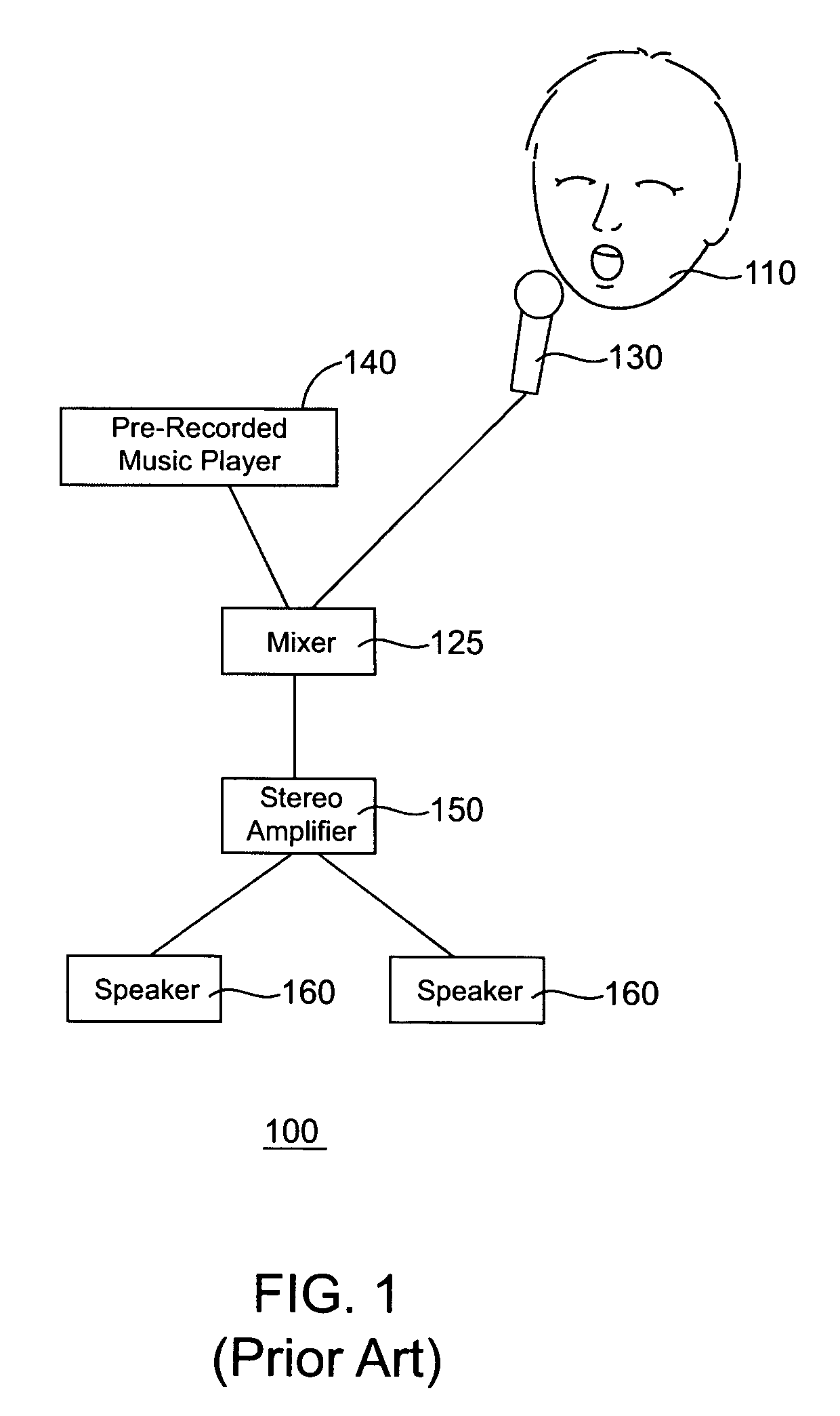
[0021]FIG. 1 shows a block diagram of a conventional karaoke sound system 100 wherein music and vocals by a user 110 are pre-mixed into one signal for speaker output. As noted above, such a convention karaoke sound system 100 comprises: a mixer 125 that combines the singer's real-time voice signal from a microphone 130 with the pre-recorded background song / music signal from a player 140 (e.g., CD player); an amplifier 150 that receives the mixed signal from the mixer 125 to provide amplification or gain boosting; and one or more speakers 160 to output the mixed and amplified audio signal. As shown, for stereo output two speakers 160 are used and for mono output one speaker 160 can be used.

[0022] In this configuration, because the vocal and music signals are pre-mixed into one signal for speaker output, the vocals tend to lack definition. Further, the vocals have to compete with the music for sound space, thereby sounding muddy, far away and without direction.

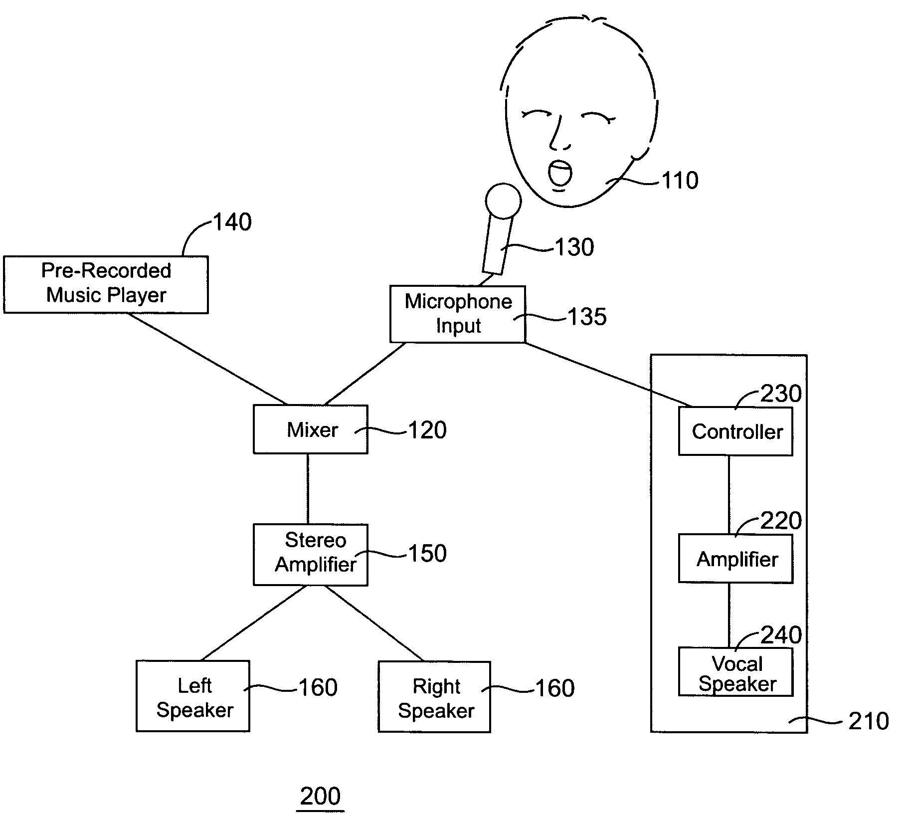
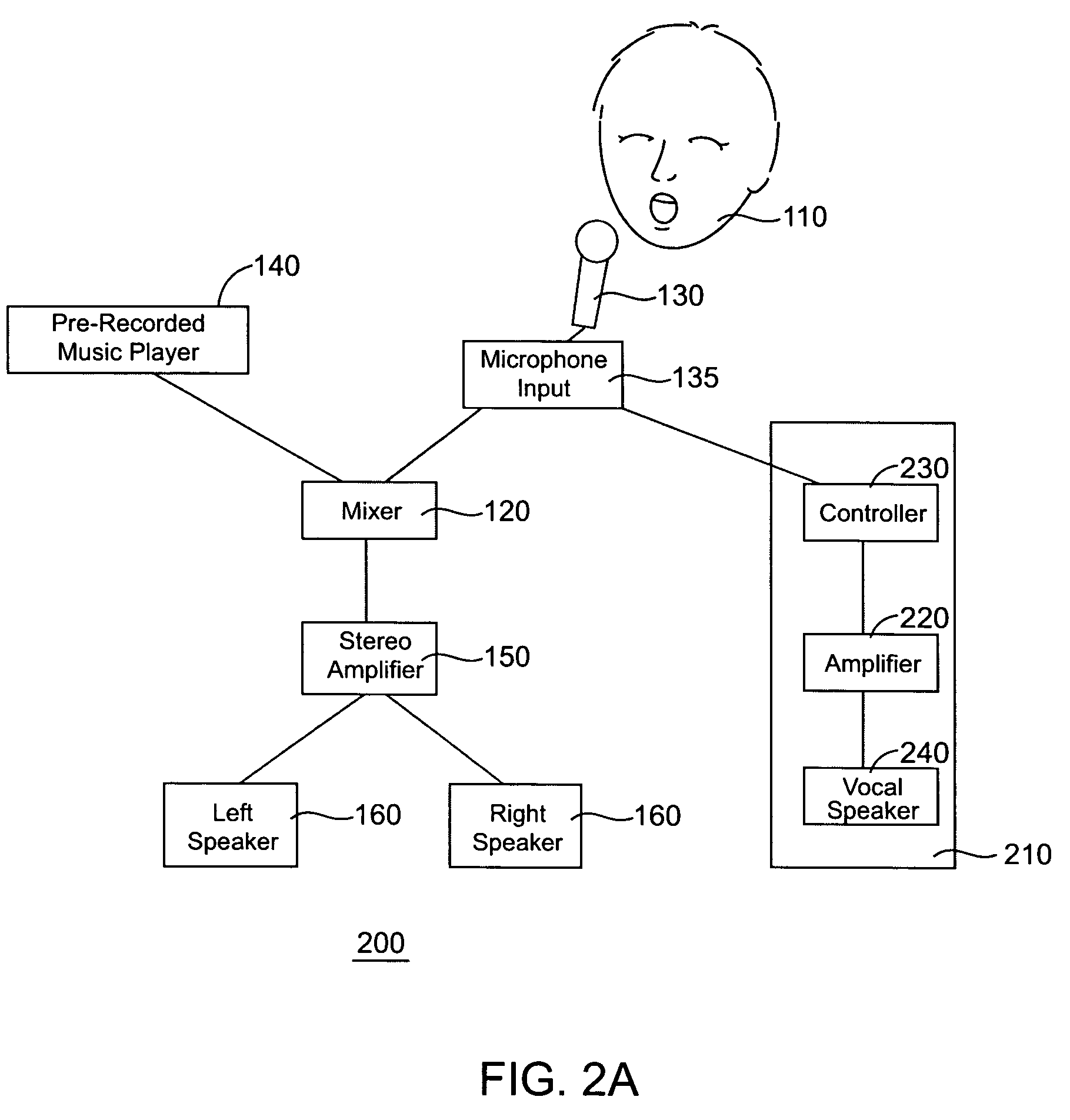
[0023]FIG. 2A shows an...


PUM


Abstract

A karaoke sound system had a mixer that combines the singer's real-time voice signal from a microphone with the pre-recorded background song / music signal from a player, an amplifier that receives the mixed signal from the mixer to provide amplification or gain boosting, a dedicated channel for the vocal signal from the microphone without using a mixing device, one or more speakers to output the mixed and amplified audio signal, and one or more speakers to output the vocal signal from the dedicated channel. The vocal channel allows the vocals to maintain an overall cleaner and vibrant sound, with a ā€œlive feelingā€ positional presence.

Description

FIELD OF THE INVENTION [0001] The present invention relates in general to karaoke, public address and audio systems and in particular to a karaoke system with a dedicated vocal channel. BACKGROUND OF THE INVENTION [0002] A conventional karaoke system plays a requested pre-recorded song that is mixed with a vocal performance of a singer. Typically, lyrics of the requested song are displayed on a monitor to aid the singer to sing along. A set of instrumental songs are played through the Karaoke system for the singer to sing along with. [0003] Such a conventional karaoke system comprises: (1) a mixer that combines the singer's real-time voice signal from a microphone with the pre-recorded background song / music signal from a player, (2) an amplifier that receives the mixed signal from the mixer to provide amplification or gain boosting, and (3) one or more speakers to output the mixed and amplified audio signal. For stereo output two speakers are used and for mono output one speaker is ...

Claims


Application Information

Patent Timeline
27 Oct 2005
Publication
US20050239030A1
IPC
G10H1/36
CPC
G10H2240/325; G10H1/361
Inventors
HOU, JASON S.C.