Louver rotation apparatus and method

Active Publication Date: 2005-11-17
HUNTER DOUGLAS INC
View PDF18 Cites 37 Cited by
  • Summary
  • Abstract
  • Description
  • Claims
  • Application Information

AI Technical Summary

Benefits of technology

[0013] The above problems and others are overcome by the herein disclosed louver rotation system. Applicants's device, by employing an elongated rack bar having user mountable gear modules adapted for user positioning in registered engagement with the gears on louver ends, both decreases the cost of the rack bar and increases the utility by providing for both gear size adjustment and location adjustment. Since the rack bar translates internally in the frame surrounding one of the two ends

Problems solved by technology

Louvers rotated in this fashion are, however, easily rotated out of the desired position by gravity, vibration, or jarring, thus presenting a constant problem in the gaps therebetween becoming too large or too small to yield the desired light transmission into the room.
The use of tilt rods also creates a visual obstruction in the center of each panel and obstructs in the cleaning of the louvers by blocking access thereto.
The use of external tilt rods also does not work well with horizontally positioned louver assemblies since the rod itself inherently wants to close the assembly if it is positioned on its top and to open the assembly if positioned on the bottom.
However, many of the available gear driven devices require the use of rods which are inflexible for fear of binding and must have gears formed along the entire surface of the elongated rod which will exactly match and engage the specific gears on the louvers.
No adjustability is provided to change both the tooth size and number and the positioning of the gears which rotate the louver gearing.
Hsu, however, requires the use of a rod having gears of a fixed

Method used


Image

  • Louver rotation apparatus and method
  • Louver rotation apparatus and method
  • Louver rotation apparatus and method

Examples


Example

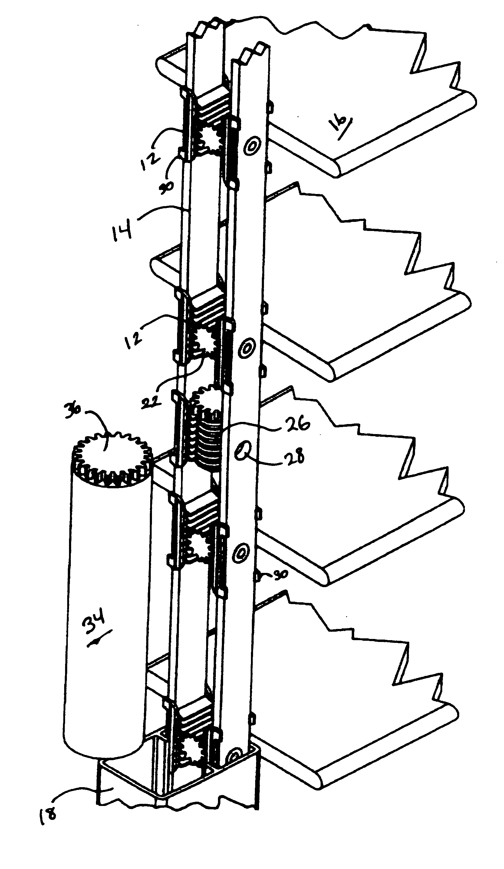
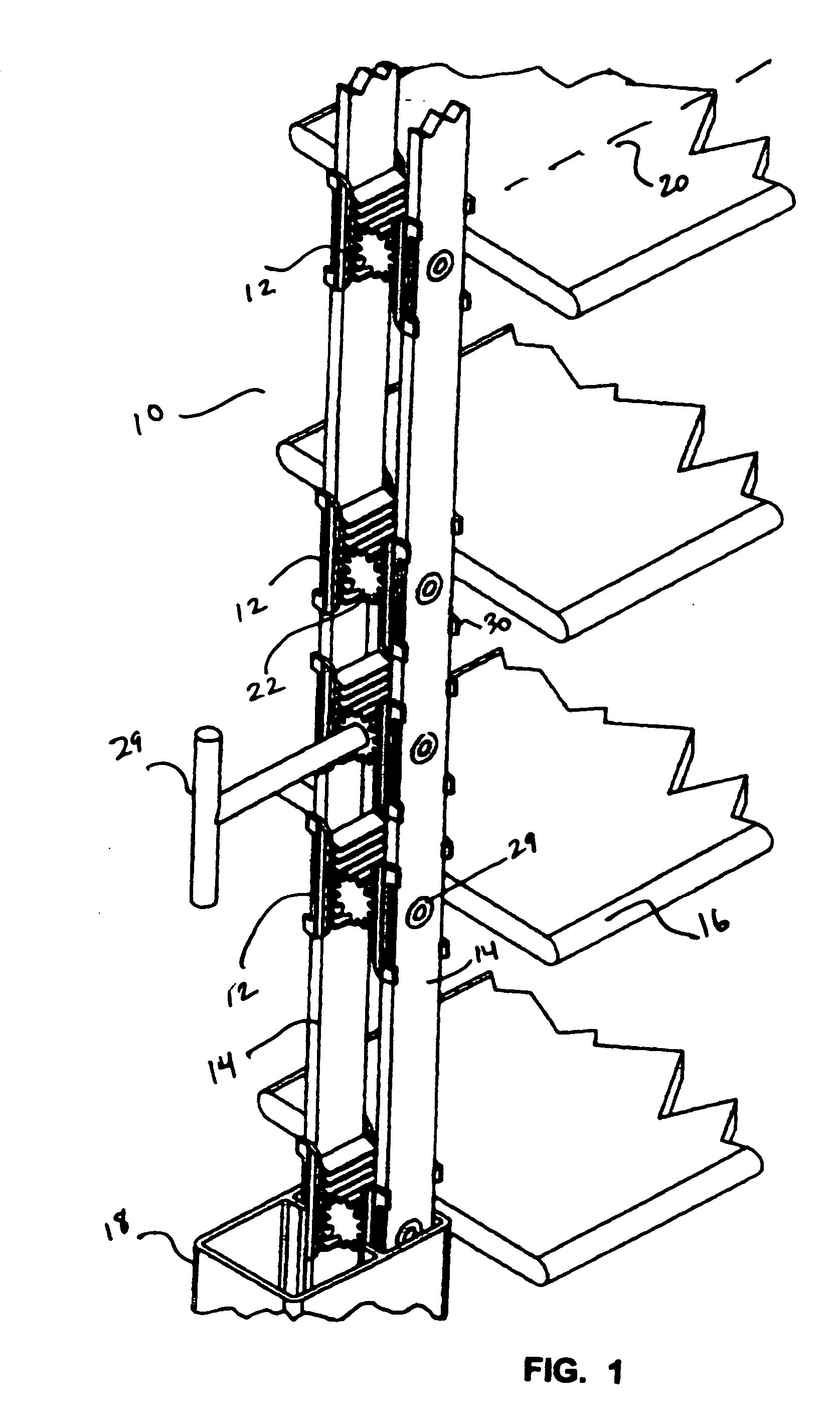
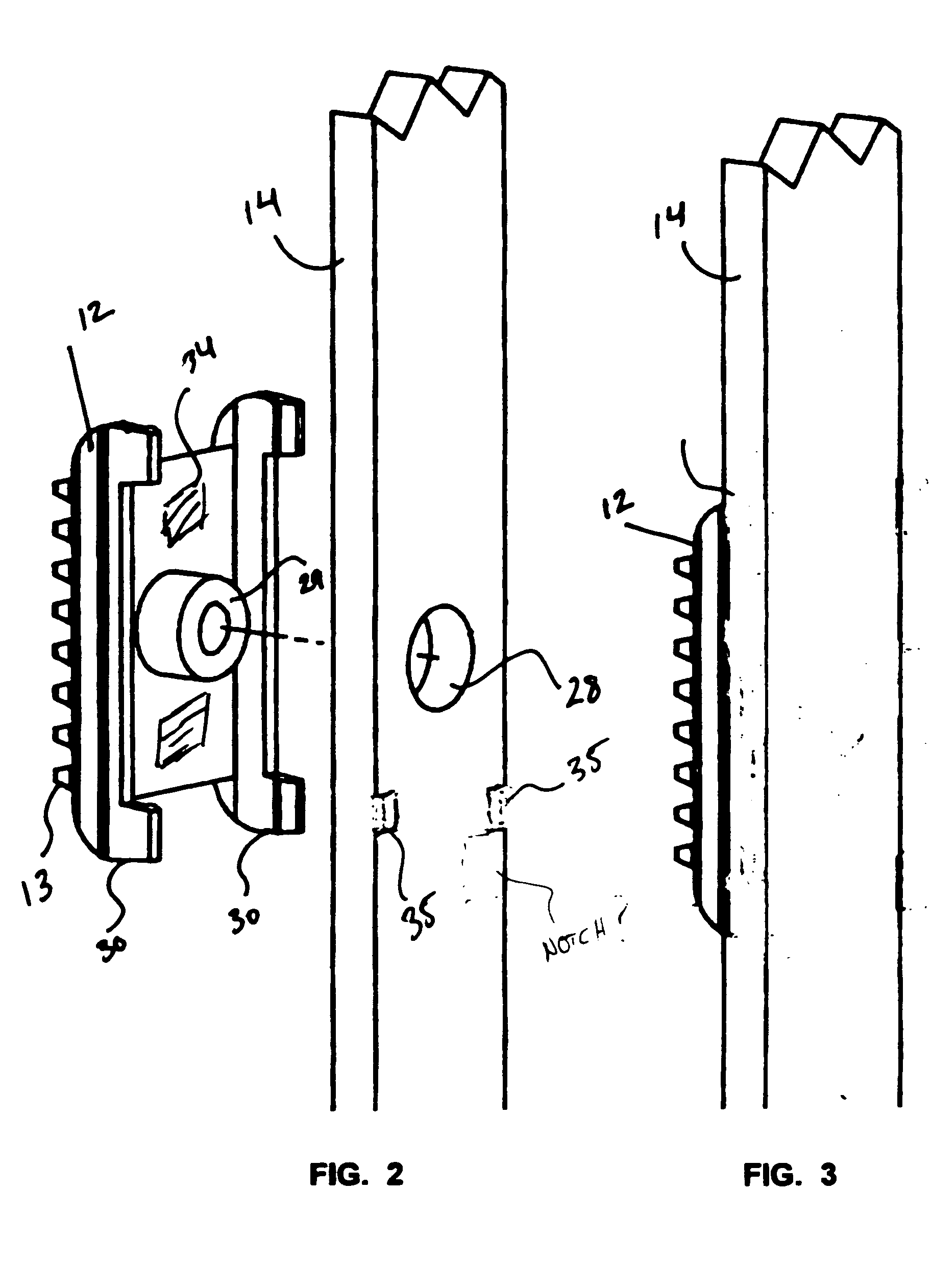
[0030] Referring now to FIGS. 1-4 which depict the current best modes and preferred embodiments of the device 10 for louver rotation. As shown, FIG. 1 depicts a perspective wherein independently positionable gear modules 12 are positioned on one or a plurality of elongated rack bars 14. Positioning of the gear modules 12 is determined by the spacing of the louvers 16 in their engagement with the frame 18 which conventionally surrounds at least both ends of the louvers 16. As noted above, louvers 16 are conventionally rotationally engaged at both ends into or through a frame 18 such that the louvers 16 will rotate in that engagement. The length of the louvers 16 is generally substantially equal and dictates the spacing of the two sidewalls forming the frame 18. The width of each louver 16 is also the same whereby the louvers may rotate from a closed position passing the least light between each parallel louver 16. In this closed position the louvers 16 generally overlap and as a cons...


PUM


Abstract

An louver rotation mechanism for use in rotating a louvered shutter having louvers rotationally engaged with a frame. The device features one or a plurality of gear modules which are positionable to a fixed location on one or a plurality of rack bars. The gear modules may be spaced on the rack bars to any number of positions wherein they will engage with louver gears from an array of louvers engaged with the frame. A high degree of customization is provided by allowing the use of the rack bars with any number of different sized louvers at different spacings in a frame by simply adjusting the positions of the rack modules for operative engagement with the louver gears.

Description

FIELD OF THE INVENTION [0001] The herein disclosed invention relates to louvered devices. More particularly it relates to a device and method for control and rotation of rotationally mounted louvers positioned vertically in windows or horizontally over skylights and patios. The disclosed and described improved rack system features racks formed by one or a plurality of user positionable gear modules attachable to operative positions on a rack bar registered to engage louver gears connected to at least one end of one or a plurality of rotatable louvers. By employing gear modules adapted for cooperative engagement at a user designated fixed position, the device provides easy customization of any length of rack to rotationally operate any number of louvers of any number of widths. Further, since the gear modules are positioned only where needed to engage a louver, the rod itself can be thin and flexible thereby allowing rods which are extremely long and can also traverse a slight curve ...

Claims


Application Information

Patent Timeline
IPC IPC(8): E06B7/096
CPCE06B7/096
Inventor YORGASON, KIM CHARLES
Owner HUNTER DOUGLAS INC
Why Eureka
Try Eureka