Microminiature power converter

Active Publication Date: 2008-07-17
FUJI ELECTRIC CO LTD
View PDF16 Cites 14 Cited by
  • Summary
  • Abstract
  • Description
  • Claims
  • Application Information

AI Technical Summary

Benefits of technology

[0030]According to the invention, wiring is formed on the coil conductors composing the thin magnetic induction element and an insulator layer interposed between the wiring and the coil conductors, and connecting (fixe) to the wiring components including

Problems solved by technology

However, since discrete parts are packaged and arranged on one and the same substrate, the reduction possible in packaging area of the power supply module is limited.
Particularly since a magnetic part, such as an inductor or a transformer, has a very large volume as compared with an integrated circuit, the size of the magnetic part constitutes the most critical limitation restricting the reduction in size and thickness of electronic equipment.
This structure, however, requires a vacuum process, which increases manufacturing costs.
In addition, it needs extensive steps for laminating a multiple of magnetic films and insulator films, especially when use at a high electric current is contemplated, which significantly increases costs.
The decreased cross-sectional area of the coil conductor and the elongated conductor wire length bring about an increase in DC resistance of the coil conductor and

Method used


Image

  • Microminiature power converter
  • Microminiature power converter
  • Microminiature power converter

Examples


Example

EXAMPLE 1

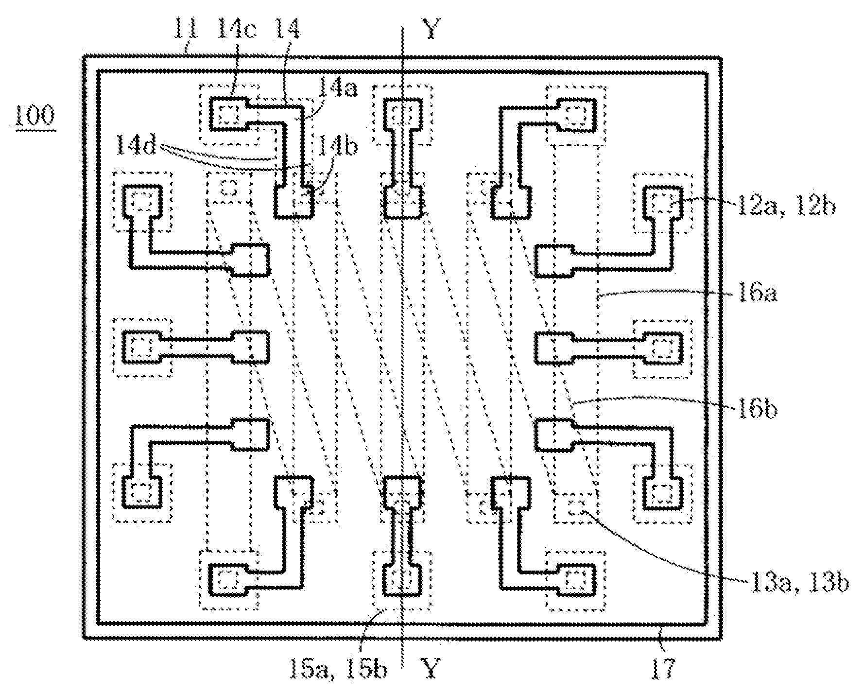
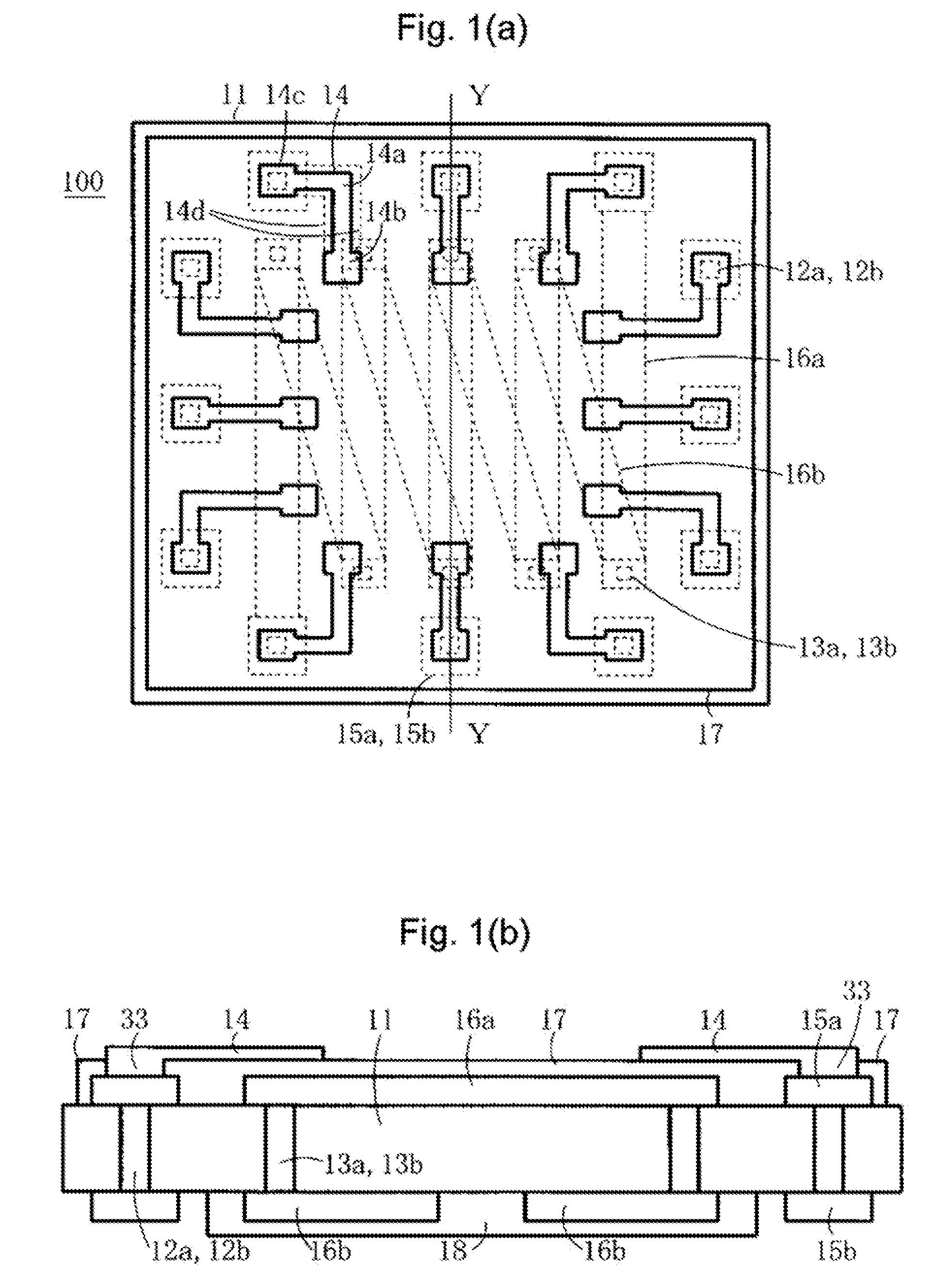
[0048]FIGS. 1(a),1(b) and 2(a), 2(b) show a structure of a microminiature power converter of a first embodiment (Example 1) of the invention, in which FIG. 1(a) is a plan view of a thin magnetic induction element seen from a first principal plane side (front side), FIG. 1(b) is a sectional view taken along the line Y-Y in FIG. 1(a), FIG. 2(a) is a plan view of a thin magnetic induction element on which a semiconductor element is packaged in a planar configuration, and FIG. 2(b) is a sectional view taken along the line Y-Y in FIG. 2(a). The semiconductor element 21 in FIGS. 2(a) and 2(b) is, for example, a power supply IC integrating a power supply controller section.

[0049]In the construction of the thin magnetic induction element 100, through-holes 12a and 13a are formed in a magnetic insulating substrate 11. Coil conductors 16a, 16b and electrodes 15a, 15b are formed on a first principal plane (front surface) and a second principal plane (rear surface) of the magnetic insu...

Example

EXAMPLE 2

[0066]FIGS. 13 and 14 show a structure of a microminiature power converter of a second embodiment (Example 2) according to the invention, in which FIG. 13 is a plan view of a thin magnetic induction element 200 seen from the first principal plane side, and FIG. 14 is a plan view in which a semiconductor element and capacitors are bonded to the wiring on the thin magnetic induction element 200 and packaged in a planar configuration.

[0067]Example 2 shows a planar packaging in which the components of one semiconductor element 21 and three capacitors 41 are bonded to the wiring 14 formed on the insulator layer 17 on the thin magnetic induction element 200. The number of components of course varies depending on the functions imparted to the microminiature power converter.

[0068]It has been difficult in the conventional peripheral electrode structure to package a plurality of elements having desired characteristics because of the restriction on the size of the semiconductor elemen...


PUM


Abstract

A microminiature power converter includes a semiconductor substrate on which a semiconductor integrated circuit is formed, and a thin magnetic induction element. The magnetic induction element includes a magnetic insulating substrate having first and second principal planes and a plurality of through-holes. A coil is formed on a central region of the magnetic insulating substrate, and electrodes are formed on the first and second principal planes at peripheral regions of the magnetic insulating substrate, and electrically connected to the magnetic insulating substrate via respective through-holes. Wiring is formed on the first principal plane in the central region of the magnetic insulating substrate and connected to a capacitor. One end of the wiring is connected to one of the electrode electrodes, and an insulator layer is provided between the wiring and the coil.

Description

CROSS-REFERENCE TO RELATED APPLICATION[0001]This application is based on, and claims priority from, Japanese Patent Application No. 2007-002966, filed on Jan. 11, 2007, the contents of which are incorporated herein by reference.BACKGROUND OF THE INVENTION[0002]1. Field of the Invention[0003]The present invention relates to a microminiaturemicrominiature power converter, such as a DC-DC converter, composed of a semiconductor element (an electronic component) such as a semiconductor integrated circuit (hereinafter referred to as an IC) and passive components such as a coil, a capacitor, and a resistor.[0004]2. Description of the Related Art[0005]Recently, electronic information equipment, various types of mobile electronic information equipment in particular, have become remarkably widespread. Most of these types of electronic information equipment have batteries for power supply and contain a power converter such as a DC-DC converter. The power converter is generally constructed as a...

Claims


Application Information

Patent Timeline
IPC IPC(8): H01F5/00
CPCH01F17/0033H01F27/29H01L2224/73204H01L2224/32225H01L2224/16225H01F27/40H01F2017/0086H01L23/49822H01L23/645H01L2924/19103H01L2924/19105H02M3/00H01L2924/00H01L2924/00014H01L2924/00011H02M3/003H01L2224/0401
Inventor EDO, MASAHARUHIROSE, TAKAYUKI
Owner FUJI ELECTRIC CO LTD
Why Eureka
Try Eureka