Clip on electronic lining wear sensor

Inactive Publication Date: 2005-04-14
ARVINMERITOR TECH
View PDF34 Cites 14 Cited by
  • Summary
  • Abstract
  • Description
  • Claims
  • Application Information

AI Technical Summary

Benefits of technology

[0005] Thus the invention offers an electronic sensor that is easy to attach to both brake shoes and brake pads by way of an inexpensive clip. Further, the sensor can be used with different vehicle braking systems simply by changing the clip,

Problems solved by technology

However, the sensor is placed at a predetermined location such that the braking surface wears away the linkage portion of the conducting member to separate the conducting member into two to break an electrical cir

Method used


Image

  • Clip on electronic lining wear sensor
  • Clip on electronic lining wear sensor
  • Clip on electronic lining wear sensor

Examples


Example

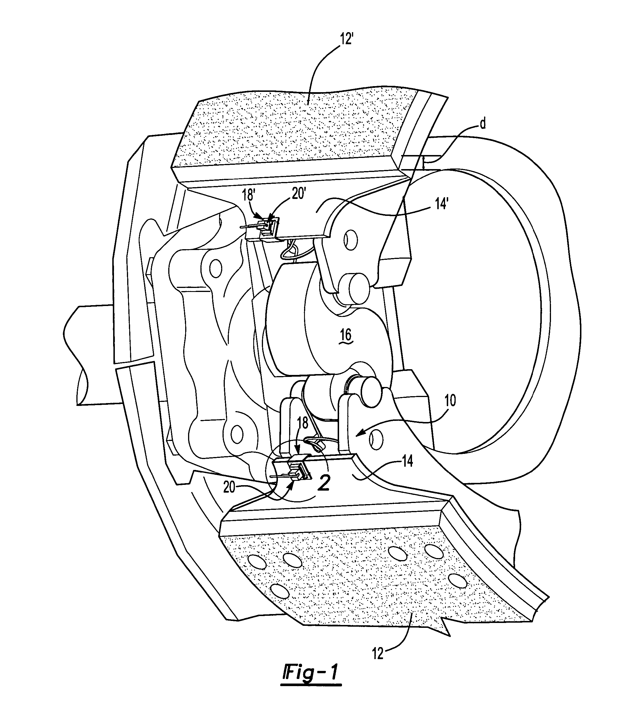
[0014]FIG. 1 shows a perspective view of a portion of a vehicle drum brake system in accordance with a first embodiment 10 of the present invention. The drum brake system includes a drum (not shown) with an inner surface (not shown) disposed about an axis of rotation A for frictionally engaging a brake lining (not shown). A pair of brake shoes 12, 12′ located adjacent the inner surface of the drum each include a backing plate comprising a table 14, 14′ and at least one brake lining segment (not shown). An actuator manipulates an S-cam 16 to move the shoes 12, 12′ into contact with the inner surface of the drum to provide a braking force, which is well known in the art.

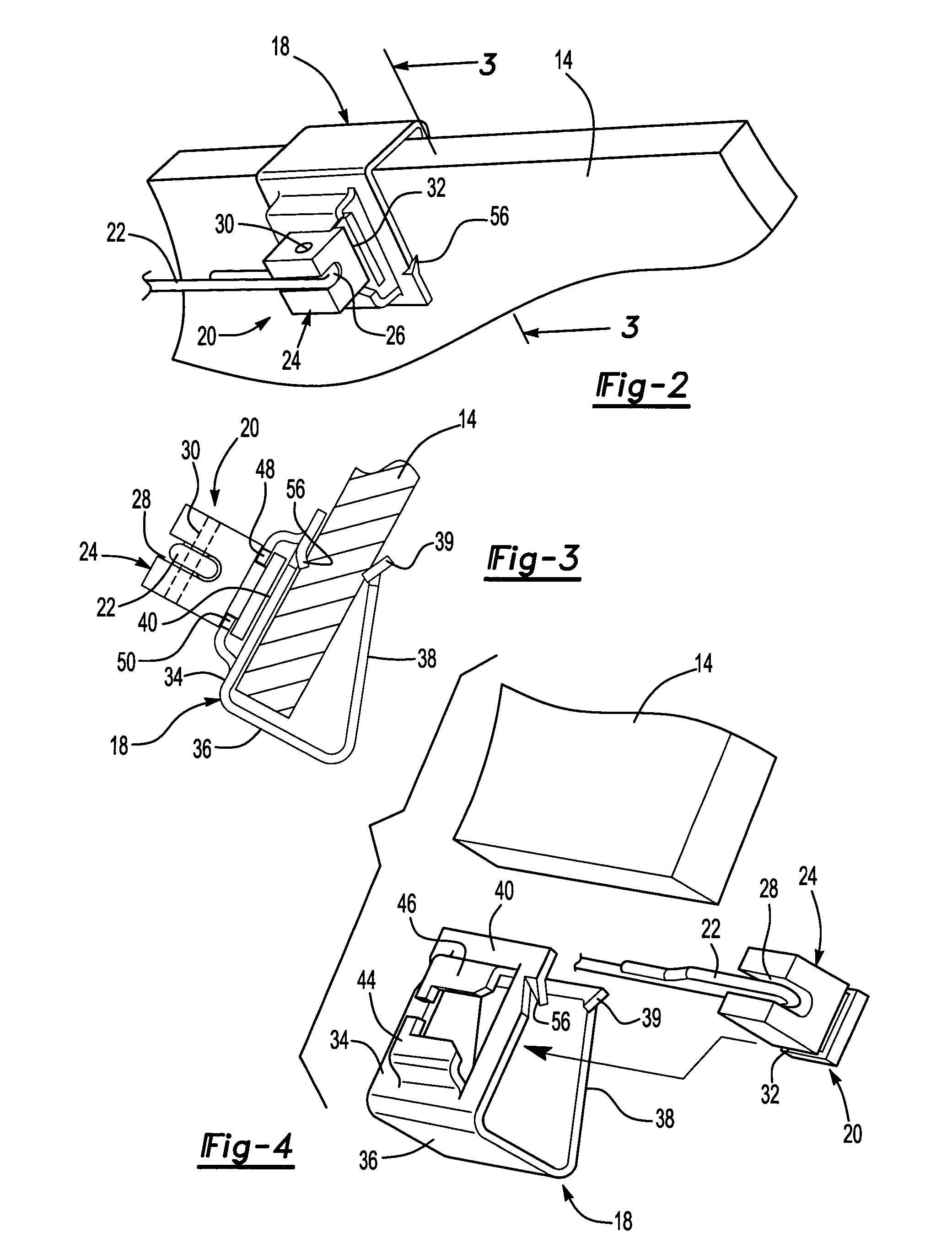
[0015] Referring to FIG. 2, a clip 18 receives a sensor 20 and attaches to the brake shoe table 14, preferably between adjacent portions of the brake lining. Throughout this description, it should be understood that an additional clip 18′ receives an additional sensor 20′ in a like manner for connection to the second ...


PUM


Abstract

An electronic sensor for a vehicle braking system comprises an electrically conducting member housed inside an insulating body. A clip is adapted to receive the sensor and attached to a braking element of the vehicle braking system, preferably between adjacent portions of a brake lining. The clip is placed at a predetermined location such that a braking surface wears down only the brake lining without contacting the conducting member until the lining is sufficiently worn. At that time, the conducting member is separated to break an electrical circuit and provide an electronic signal.

Description

BACKGROUND OF THE INVENTION [0001] This invention relates to electronic wear detection probes or sensors for vehicle braking elements. [0002] Brake lining wear sensors are well known and used in the prior art. Brake shoes and brake pads are composed of a suitable friction lining material mounted onto a metal back plate or table. The lining contacts the disc or drum, creates drag, and slow down the vehicle. Over time, the contact between the lining and the disc or drum causes the lining to wear. Thus it is desirable to provide an indication of when brake lining thickness is sufficiently worn to warrant changing of the lining. [0003] Typical electronic sensors that act as indicators are expensive and somewhat difficult to attach to brake shoes or pads. Such sensors are often molded directly into the brake lining material and therefore must be designed for use with a specific brake shoe or pad. This makes it very difficult, if not impossible, to modify a sensor manufactured for use on ...

Claims


Application Information

Patent Timeline
IPC IPC(8): F16D55/00F16D66/02
CPCF16D66/021
Inventor HARRIS, BRUCE V.KAY, JOSESPH A.CORY, THOMAS MICHAEL
Owner ARVINMERITOR TECH
Why Eureka
Try Eureka