

Braking apparatus
- Summary
- Abstract
- Description
- Claims
- Application Information
AI Technical Summary
Benefits of technology
Problems solved by technology
Method used
Image

Examples
first embodiment
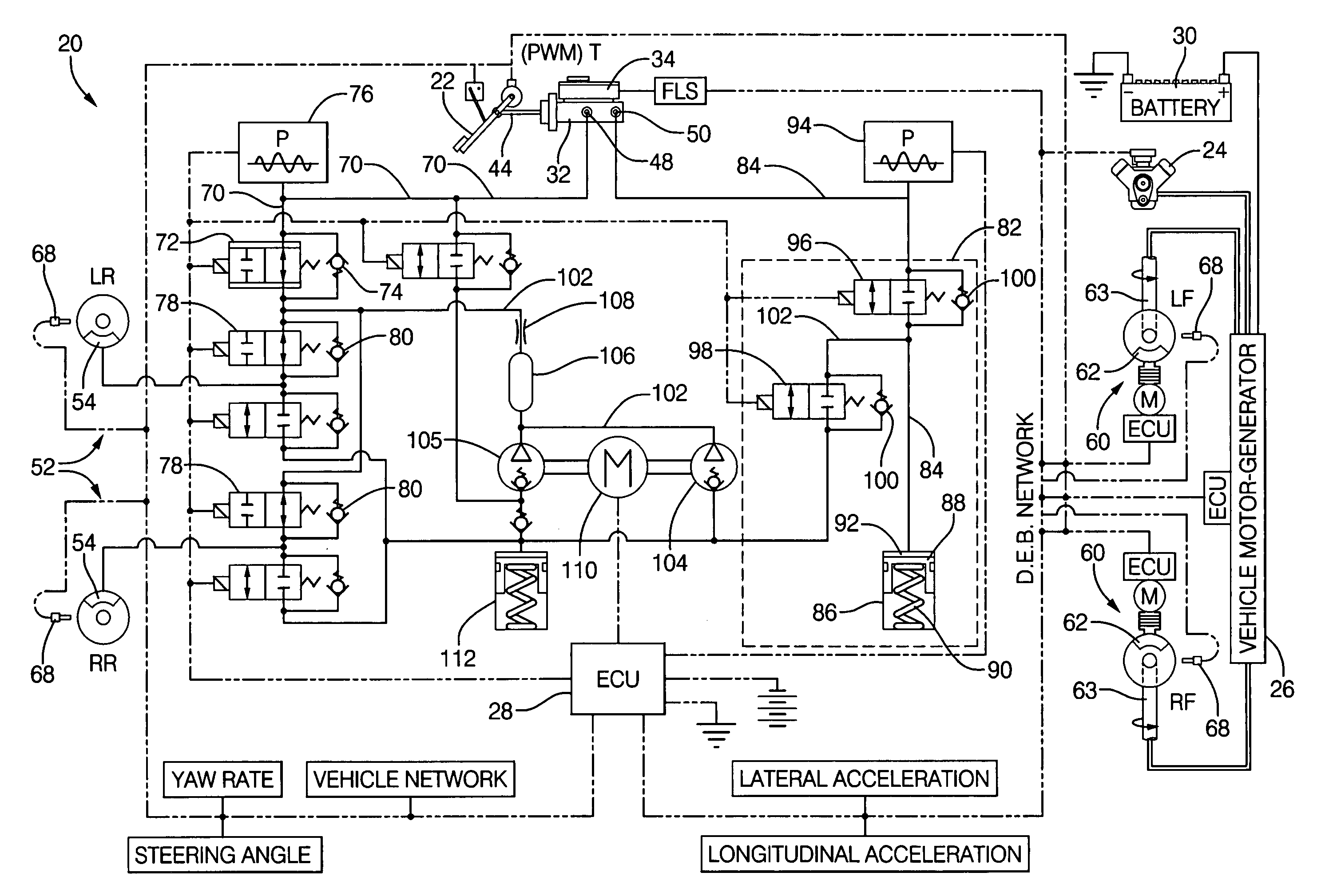
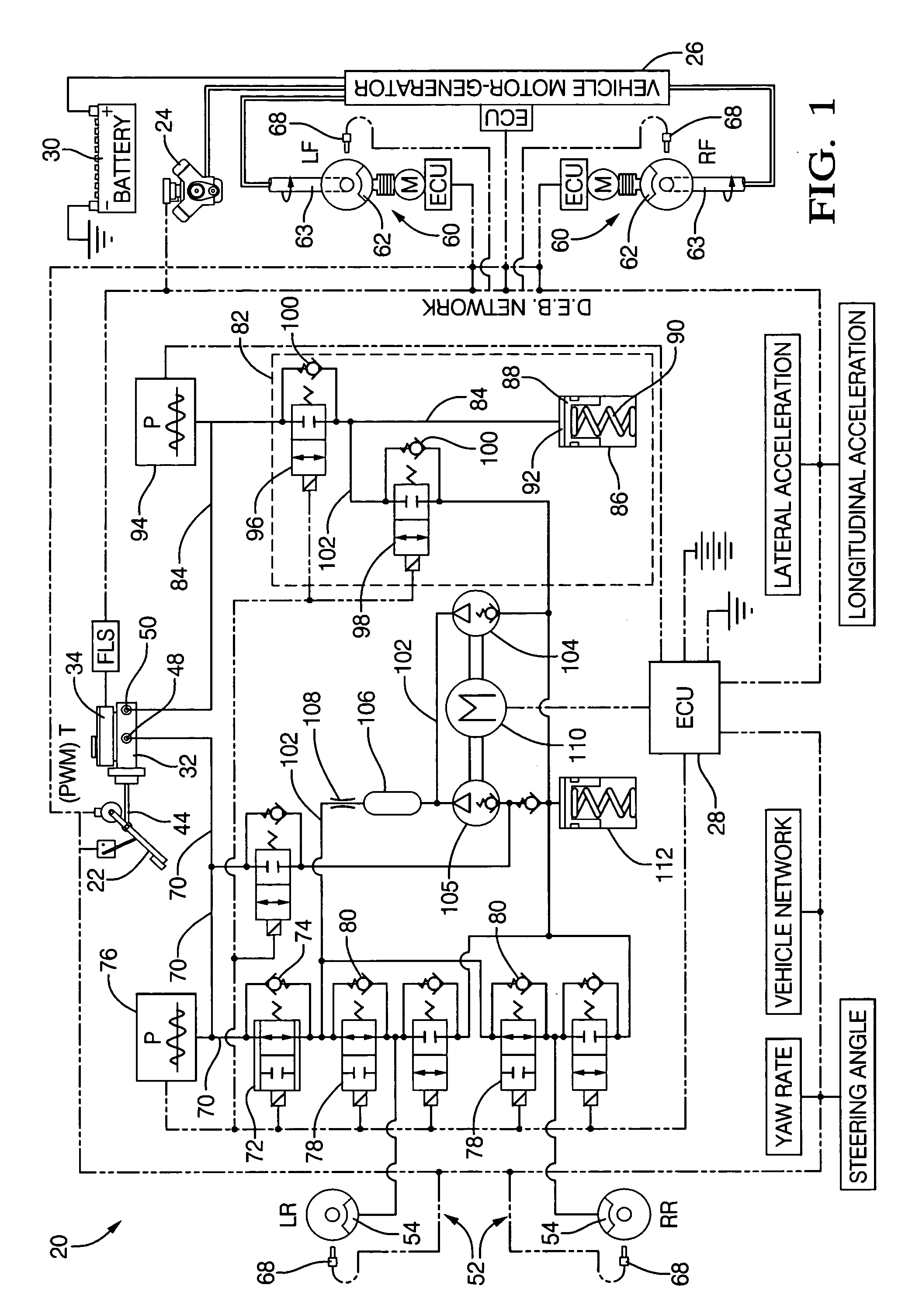
[0034]In the braking apparatus 20 as shown in FIGS. 1 and 3, the replenishment system 82 further includes a first valve also referred to as an emulator inlet valve 96 and a second valve also referred to as an emulator outlet valve 98 in electrical communication with the control unit 28. The emulator inlet valve 96 and the emulator outlet valve 98 each have a check valve 100 for providing one way flow of the brake fluid. The emulator inlet valve 96 is in fluid communication with the master cylinder 32 and the emulator 86 for providing flow of the brake fluid to the emulator 86. Preferably, the brake fluid flows in one direction from the master cylinder 32 to the emulator 86 due to pressure within the second fluid line 84 and each of the check valves 100 of the emulator inlet valve 96 and the emulator outlet valve 98. The emulator inlet valve 96 and the emulator 86 are disposed along the second fluid line 84 for feeding the brake fluid from the master cylinder 32 to the emulator 86 du...
second embodiment
[0040]As shown in FIGS. 4-10, the braking apparatus 20 is shown wherein like numerals indicate like or corresponding parts throughout the several views. The braking apparatus 20 includes the third fluid line 102 coupled to the second fluid line 84 at a first position 114 and a second position 116. As best shown in FIG. 4, the first position 114 is disposed between the emulator inlet valve 96 and the emulator 86 and the second position 116 is disposed between the master cylinder 32 and the emulator inlet valve 96 on the second fluid line 84. The pump 104 is disposed along the third fluid line 102 for pumping the brake fluid out of the emulator 86 and into the hydraulic brake 54. The damper chamber 106 and the orifice 108 are disposed along the third fluid line 102 for aiding in the delivery the brake fluid to the hydraulic brakes 54.
[0041]Referring to FIGS. 5 and 8, a partial schematic view of the braking apparatus 20 is shown before the brake pedal 22 is depressed, wherein the brake...
PUM
 Abstract
Description
Claims
Application Information