Light projection rotary control indicator

a technology of rotary control and light projection, which is applied in the direction of mechanical control devices, lighting and heating apparatus, instruments, etc., can solve the problems of difficult for the disk jockey to see into the darkened room, the difficulty of disc jockeys to illuminate the control of disk jockey mixers and other similar equipment, and the inability to adequately address the problem of allowing the disk jockey to enter the darkened room

Inactive Publication Date: 2005-12-08
STANTON MAGNETICS
View PDF9 Cites 4 Cited by
  • Summary
  • Abstract
  • Description
  • Claims
  • Application Information

AI Technical Summary

Benefits of technology

[0006] It is therefore an object of the present invention to provide a knob, or rotary control indicator, which

Problems solved by technology

In the prior art, it has been problematic to illuminate the controls on disk jockey mixers and other similar equipment in a dark night club, dance club, or similar establishment, for use by a disk jockey.
However, this light is often a distraction and makes it difficult for the disk jockey to see into

Method used


Image

  • Light projection rotary control indicator
  • Light projection rotary control indicator

Examples


Embodiment Construction

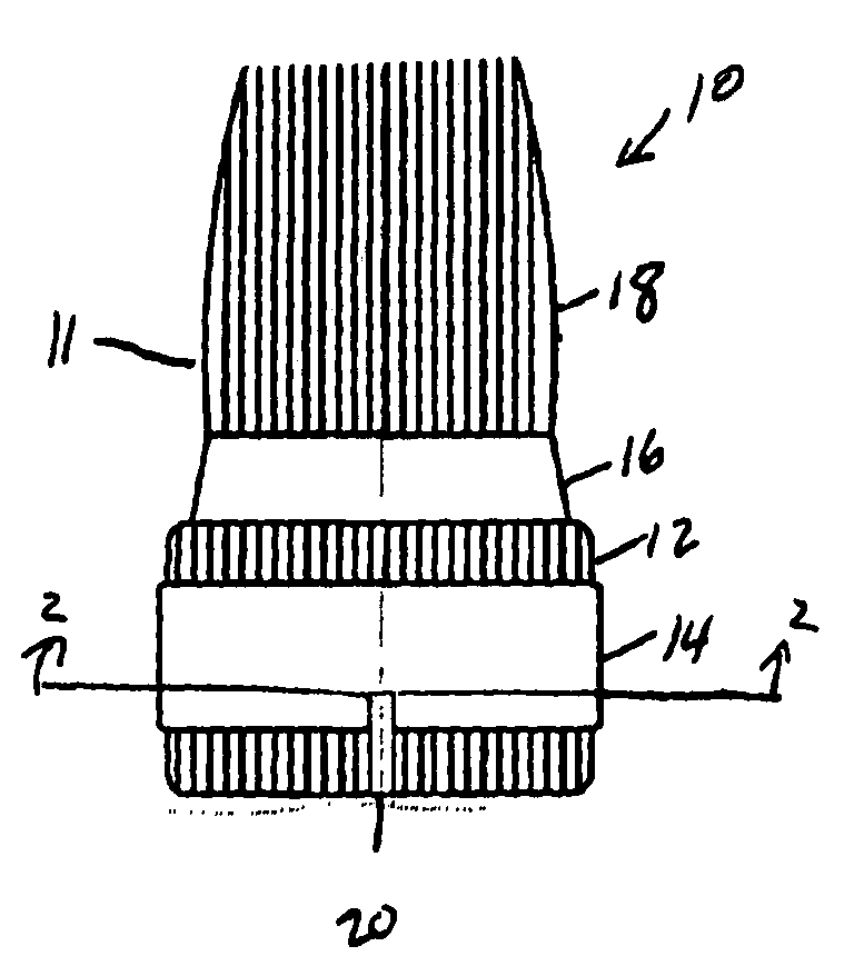
[0016] Referring now to the drawings in detail, wherein like numerals indicate like elements throughout the several views, one sees that FIG. 1 is a side plan view of the knob portion 11 of rotary control indicator 10 of the present invention, visible above the control panel. While a wide range of profiles may be used for the knob portion 11, the illustrated knob portion 11 includes a cylindrical ribbed base 12 with a central band 14. A truncated portion of a cone 16 extends from base 12 to ribbed gripping area 18. Notch 20 is radially formed on a lower portion of central band 14 and the portion of cylindrical ribbed base 12 below central band 14. FIG. 2 is a cross-sectional view showing the depth of notch 20.

[0017]FIG. 3 is a side cross-sectional view, partly in phantom, of the rotary control indicator 10. Potentiometer 30 is mounted on printed circuit board 200 and includes clear shaft 32 which extends through aperture 101 of control panel 100 and is connected to knob portion 11....


PUM


Abstract

A rotary control indicator includes a knob with a reflective interior. The knob rotates in concert with a clear shaft which receives light from an LED. The knob further includes a radial notch. Light is reflected by the reflective interior to illuminate the control panel around a periphery of the knob. Further, light is projected out the radial notch to indicate the knob position.

Description

BACKGROUND OF THE INVENTION [0001] 1. Field of the Invention [0002] This invention pertains to a rotary control indicator, such as a knob for an electronic music apparatus, such as a disk jockey mixer. A light source is emitted through the shaft of the knob so that the light is reflected from the interior of the knob toward the control panel. As there is clearance between the knob and the control panel, the illumination of the control panel is visible to the user of the apparatus. Further, there is a notch in the knob so that some light is reflected radially outward from the knob toward the control panel, to serve as an indicator of knob position. [0003] 2. Description of the Prior Art [0004] In the prior art, it has been problematic to illuminate the controls on disk jockey mixers and other similar equipment in a dark night club, dance club, or similar establishment, for use by a disk jockey. Moreover, as disk jockeys are considered to be performers, it is desirable for the equipme...

Claims


Application Information

Patent Timeline
IPC IPC(8): G05G1/10G01D11/28
CPCG01D11/28G05G1/105
Inventor MAZUR, JAMES
Owner STANTON MAGNETICS
Why Eureka
Try Eureka