Push type switch
- Summary
- Abstract
- Description
- Claims
- Application Information
AI Technical Summary
Benefits of technology
Problems solved by technology
Method used
Image
Examples
first embodiment
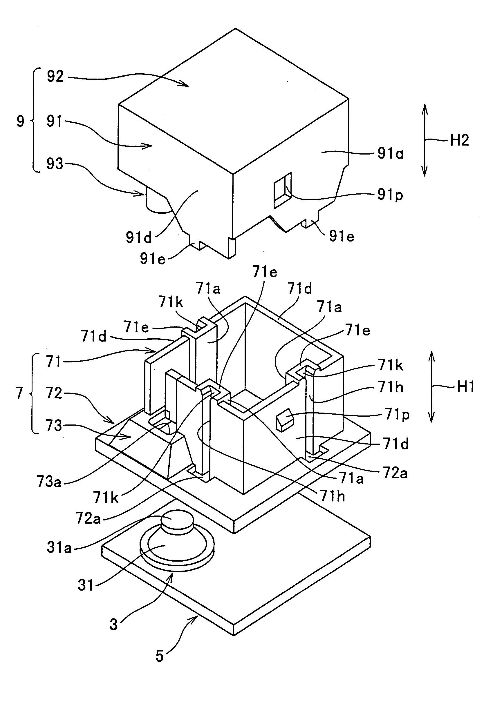
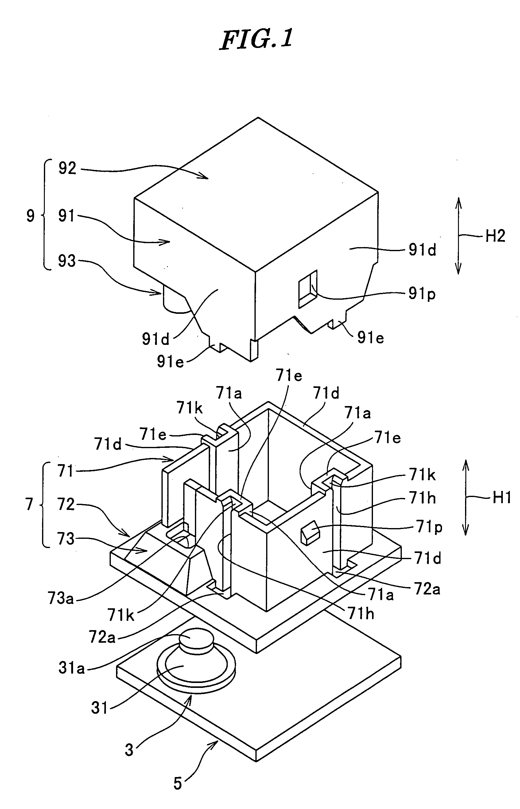
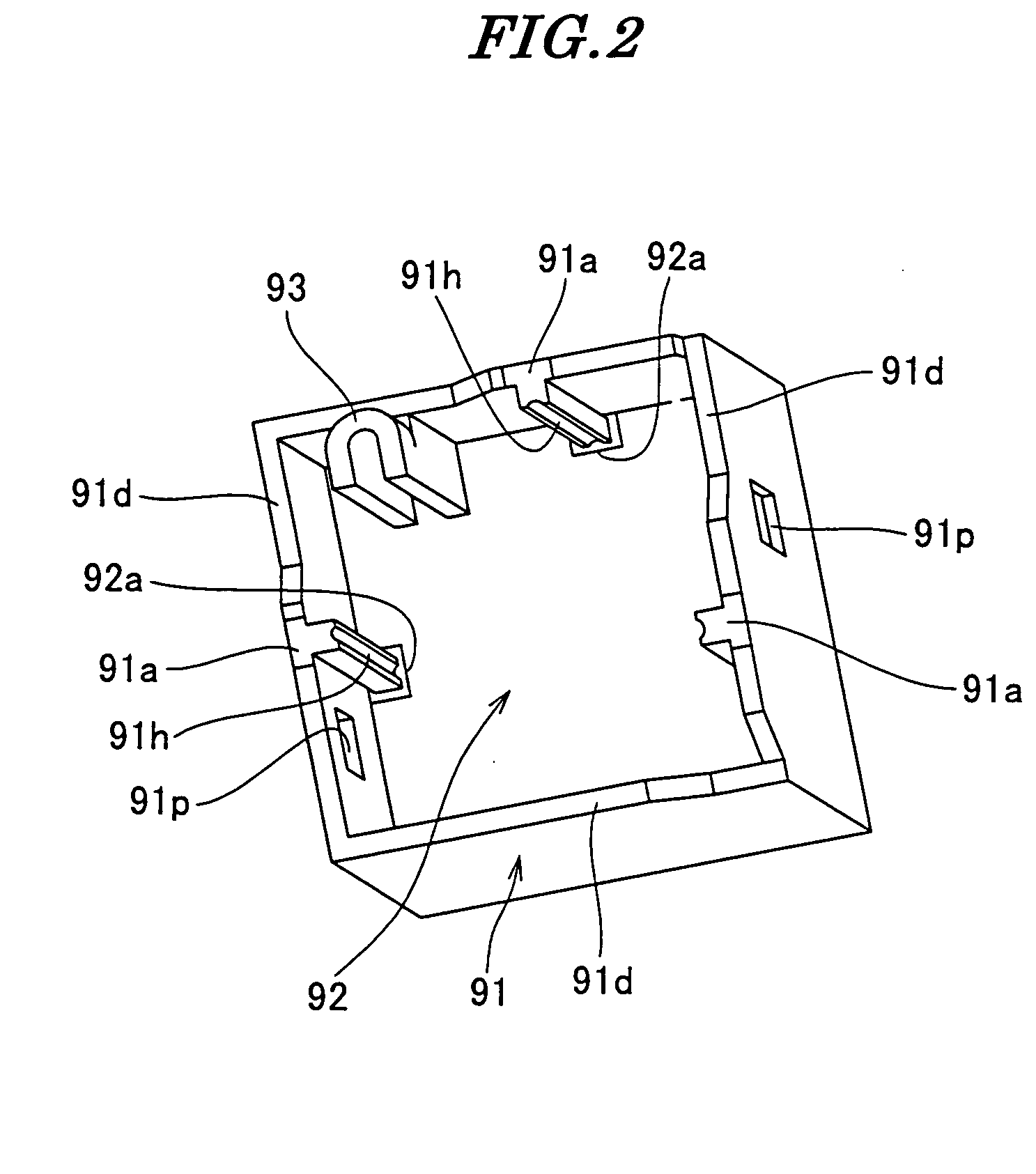
[0058]FIG. 1 is an exploded perspective view of a push type switch according to the present invention; FIG. 2 is a perspective view of a knob of the FIG. 1 push type switch, as viewed obliquely from below; FIG. 3A is a front view of the FIG. 1 push type switch; FIG. 3B is a plan view of the FIG. 1 push type switch; FIG. 3C is a bottom view of the FIG. 1 push type switch; FIG. 3D is a right side view of the FIG. 1 push type switch; FIG. 4 is a cross-sectional view taken on line IV-IV of FIG. 3A; FIG. 5 is a cross-sectional view taken on line V-V of FIG. 3D; and FIG. 6 is an enlarged view of part A appearing in FIG. 5.
[0059] As shown in FIGS. 1 to 6, the push type switch is comprised of a switch body 3, a printed wiring board 5, a casing 7, and a knob (movable member) 9.
[0060] The switch body 3 is disposed at a corner of the printed wiring board 5. The switch body 3 includes a click board 31, a pair of fixed contact points (not shown), and a movable contact point (not shown). The cli...
second embodiment
[0141]FIG. 23 is an exploded perspective view of a push type switch according to the present invention; FIG. 24 is a perspective view of the FIG. 23 push type switch, in a state having part of a casing thereof cut off, and presented in an inverted position; FIG. 25 is an enlarged view of part B appearing in FIG. 24; and FIG. 26 is a cross-sectional view of the FIG. 23 push type switch.
[0142] Component parts identical to those of the first embodiment are designated by identical reference numerals, and detailed description thereof is omitted, while only component parts different in configuration from the first embodiment will be described hereinafter.
[0143] As shown in FIGS. 23 to 26, the push type switch is comprised of a switch body 3, a printed wiring board 5, a casing 207, a knob 209, and a slider 210.
[0144] As distinct from the first embodiment in which the movable member is formed by the knob 9 alone, in the second embodiment, a movable member is formed by the knob 209 and the...
PUM
 Abstract
Description
Claims
Application Information
 - R&D
- Intellectual Property
- Life Sciences
- Materials
- Tech Scout
- Unparalleled Data Quality
- Higher Quality Content
- 60% Fewer Hallucinations
Browse by: Latest US Patents, China's latest patents, Technical Efficacy Thesaurus, Application Domain, Technology Topic, Popular Technical Reports.
© 2025 PatSnap. All rights reserved.Legal|Privacy policy|Modern Slavery Act Transparency Statement|Sitemap|About US| Contact US: help@patsnap.com


