Push type switch

a push-type switch and switch technology, applied in the direction of tactile feedback, contact mechanisms, electrical appliances, etc., can solve the problem of limiting the creation of upscale impressions

Inactive Publication Date: 2014-07-01
JAPAN AVIATION ELECTRONICS IND LTD
View PDF9 Cites 4 Cited by
  • Summary
  • Abstract
  • Description
  • Claims
  • Application Information

AI Technical Summary

Benefits of technology

[0016]The present invention has been made in view of these circumstances, and an object thereof is to provide a push type switch which is capable of causing an operator to sense an upscale impression when he operates the push type switch.
[0018]According to this push type switch, the viscosity of the grease is within a range of 1000 to 2750 Pa, so that when an operator pushes the movable member with his finger, he feels that an appropriate weight (a force his fingertip receives from the grease) is transmitted to his fingertip, and recognizes that the movable member is moved more slowly than in the prior art. Further, the operator can feel that rattling of the movable member and generation of noise are more suppressed than in the prior art. As a result, the push type switch according to the present invention is capable of giving an upscale impression to the operator when he operates the push type switch.
[0020]According to this preferred embodiment, since the grease is a fluorine-based grease, no significant changes in the viscosity are caused by temperature. As a result, it is possible to prevent the operation feeling from being changed due to changes in temperature.
[0022]According to this preferred embodiment, a guide groove is formed in one of the fixing member and the movable member, and a rail for sliding relative to the guide groove is formed on the other of the fixing member and the movable member. Therefore, the movable member can slide more stably. Further, according to the present invention, it is possible to further enhance the upscale impression during operation of the push type switch.
[0024]According to this preferred embodiment, since a first grease reservoir is formed in at least one of the guide groove and the rail, loss of the grease is caused only in a small amount even after the push type switch is used for a long time period. This makes it possible to maintain an excellent operation feeling for a long time period.
[0026]According to this preferred embodiment, since a second grease reservoir is formed in one end of either the guide groove or the rail, loss of the grease is caused only in a small amount even after the push type switch is used for a long time period. This makes it possible to maintain an excellent operation feeling for a long time period.

Problems solved by technology

However, there was a limit to creating the upscale impression, unless an operation feeling in operating the key switch is enhanced.

Method used


Image

  • Push type switch
  • Push type switch
  • Push type switch

Examples


first embodiment

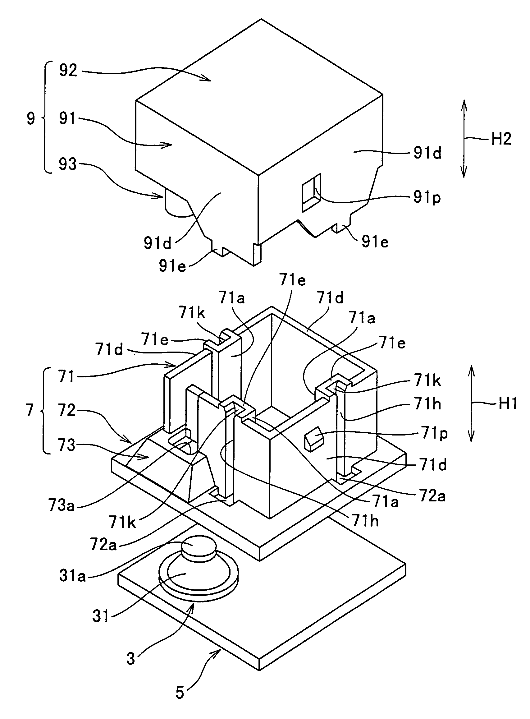
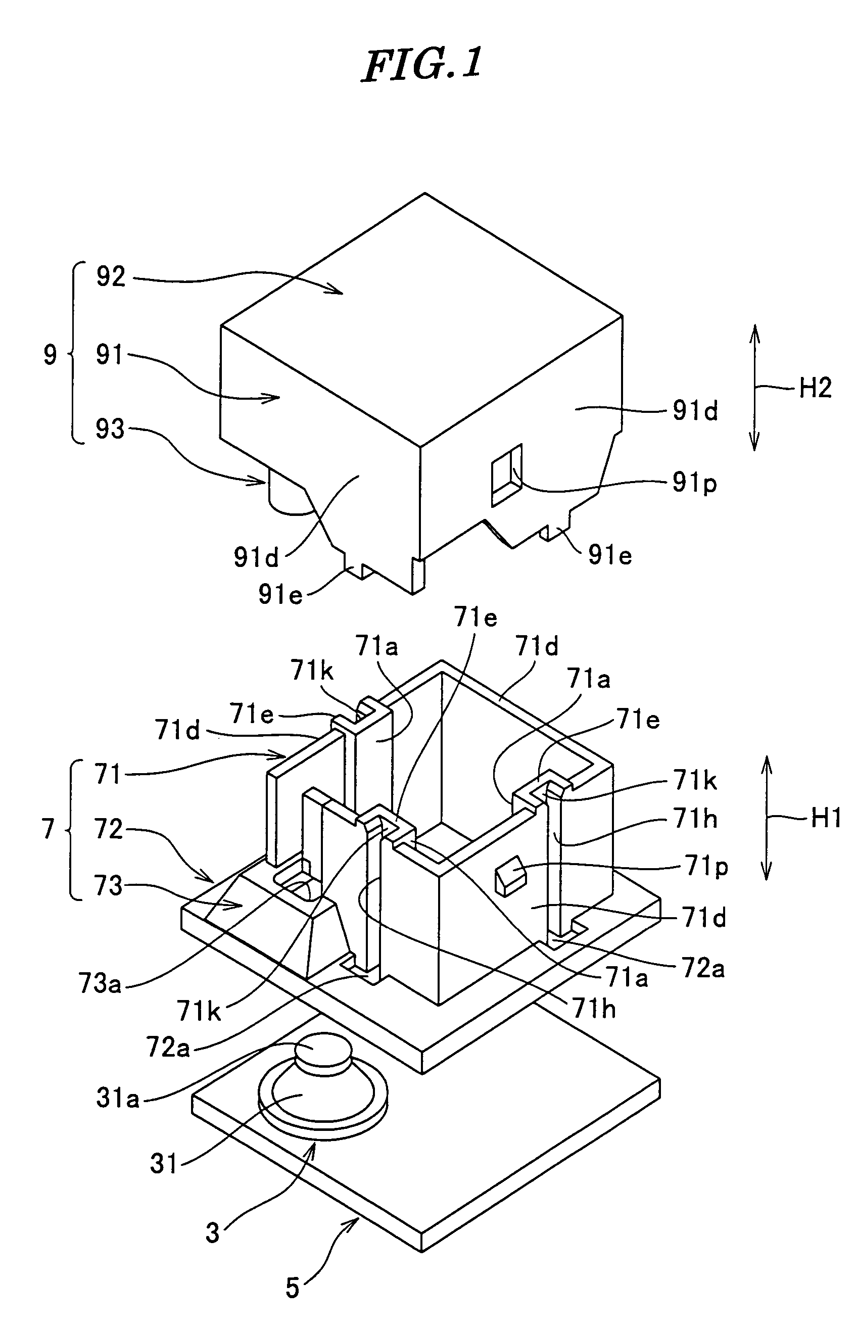
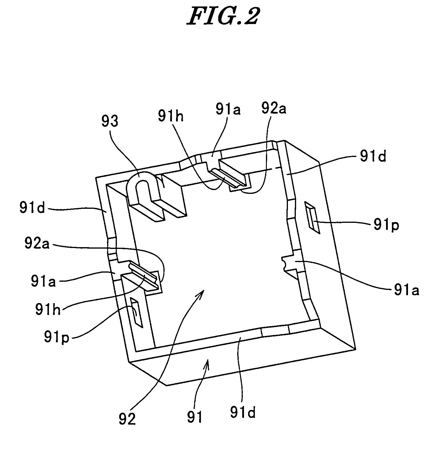
[0058]FIG. 1 is an exploded perspective view of a push type switch according to the present invention; FIG. 2 is a perspective view of a knob of the FIG. 1 push type switch, as viewed obliquely from below; FIG. 3A is a front view of the FIG. 1 push type switch; FIG. 3B is a plan view of the FIG. 1 push type switch; FIG. 3C is a bottom view of the FIG. 1 push type switch; FIG. 3D is a right side view of the FIG. 1 push type switch; FIG. 4 is a cross-sectional view taken on line IV-IV of FIG. 3A; FIG. 5 is a cross-sectional view taken on line V-V of FIG. 3D; and FIG. 6 is an enlarged view of part A appearing in FIG. 5.

[0059]As shown in FIGS. 1 to 6, the push type switch is comprised of a switch body 3, a printed wiring board 5, a casing 7, and a knob (movable member) 9.

[0060]The switch body 3 is disposed at a corner of the printed wiring board 5. The switch body 3 includes a click board 31, a pair of fixed contact points (not shown), and a movable contact point (not shown). The click ...

second embodiment

[0142]FIG. 23 is an exploded perspective view of a push type switch according to the present invention; FIG. 24 is a perspective view of the FIG. 23 push type switch, in a state having part of a casing thereof cut off, and presented in an inverted position; FIG. 25 is an enlarged view of part B appearing in FIG. 24; and FIG. 26 is a cross-sectional view of the FIG. 23 push type switch.

[0143]Component parts identical to those of the first embodiment are designated by identical reference numerals, and detailed description thereof is omitted, while only component parts different in configuration from the first embodiment will be described hereinafter.

[0144]As shown in FIGS. 23 to 26, the push type switch is comprised of a switch body 3, a printed wiring board 5, a casing 207, a knob 209, and a slider 210.

[0145]As distinct from the first embodiment in which the movable member is formed by the knob 9 alone, in the second embodiment, a movable member is formed by the knob 209 and the slid...


PUM


Abstract

A push type switch which enables an operator to obtain an upscale impression when he operates the push type switch. A switch body 3 is rigidly fixed to a printed wiring board 5. A casing 7 having a plurality of guide grooves 71h is fixed to the printed wiring board 5. A plurality of rails 91a provided on a knob 9 capable of transmitting a pushing force to the switch body 3 are slidably inserted into the guide grooves 71h such that the knob 9 can slide on the casing 7. A grease is applied to the guide grooves 71h and the rails 91a. The viscosity of the grease is set to be within a range of 1000 to 2750 Pa.

Description

BACKGROUND OF THE INVENTION[0001]1. Field of the Invention[0002]The present invention relates to a push type switch, and more particularly to a push type switch which is capable of creating an upscale impression when operating (pushing) the push type switch.[0003]2. Description of the Related Art[0004]Conventionally, a key switch is known which is comprised of a membrane substrate, a pair of fixed contact points, a click rubber, a frame, and a key top (see e.g. Japanese Laid-Open Patent Publication (Kokai) No. 2004-71306 (Paragraph numbers [0011] to [0014], FIG. 1))[0005]The membrane substrate is disposed on a chassis e.g. of electronic equipment.[0006]The pair of fixed contact points are provided on the membrane substrate.[0007]The click rubber has a generally domed shape, and covers the pair of fixed contact points. The click rubber has a conductive rubber provided on an inner surface thereof. The conductive rubber is opposed to the pair of fixed contact points in a manner spaced ...

Claims


Application Information

Patent Timeline
Patent Type & Authority Patents(United States)
IPC IPC(8): H01H3/12H01H3/62H01H13/14H01H13/20
CPCH01H13/20H01H3/62H01H2215/004
Inventor TAKIGUCHI, TSUYOSHIIWAO, NAOKI
Owner JAPAN AVIATION ELECTRONICS IND LTD
Why Eureka
Try Eureka