Motorcycle dolly

a dolly and motorcycle technology, applied in the field of motorcycle dolly, can solve the problems of difficult storage of motorcycles and other two-wheeled vehicles, increased side-to-side space for motorcycles, and inherently unstable motorcycles

Inactive Publication Date: 2005-12-29
JOHNSON CHARLES RICHARD
View PDF10 Cites 19 Cited by
  • Summary
  • Abstract
  • Description
  • Claims
  • Application Information

AI Technical Summary

Problems solved by technology

Motorcycles and other two-wheeled vehicles are difficult to store.
For example, motorcycles are inherently unstable, and tend to tip in direction opposite the plane in which their wheels rotate.
However, the motorcycle fills more side-to-side space when in the partially-upright inclined position afforded by the kick-stand.
The additional side-to-side space required when using the kick-stand can pose a problem when storing a motorcycle.
Either way, whether the kick-stand was positioned on the left-hand or right-hand side of the motorcycle, it would be difficult to park the motorcycle against a wall of a garage.
In some garages, such positioning is not possible, and the motorcycle must be parked near the center of the garage.
In addition to being difficult to store, a motorcycle can be difficult to move around.
The turning radius of the motorcycle, while ideal for driving conditions, is not suited to allow for repositioning of the motorcycle in a tight space.
For example, if a motorcycle is driven into a garage forwards, then it can be difficult to turn the motorcycle around in a garage.
The tight space of most garages will not afford the space necessary for the motorcycle to make a complete turn.
Such back and forth movement requires space which may not be available in a garage.
As such, a motorcycle or other similar two-wheeled vehicle is difficult to store, and requires space for repositioning which may not be available in the place it is stored.

Method used


Image

  • Motorcycle dolly
  • Motorcycle dolly
  • Motorcycle dolly

Examples


Embodiment Construction

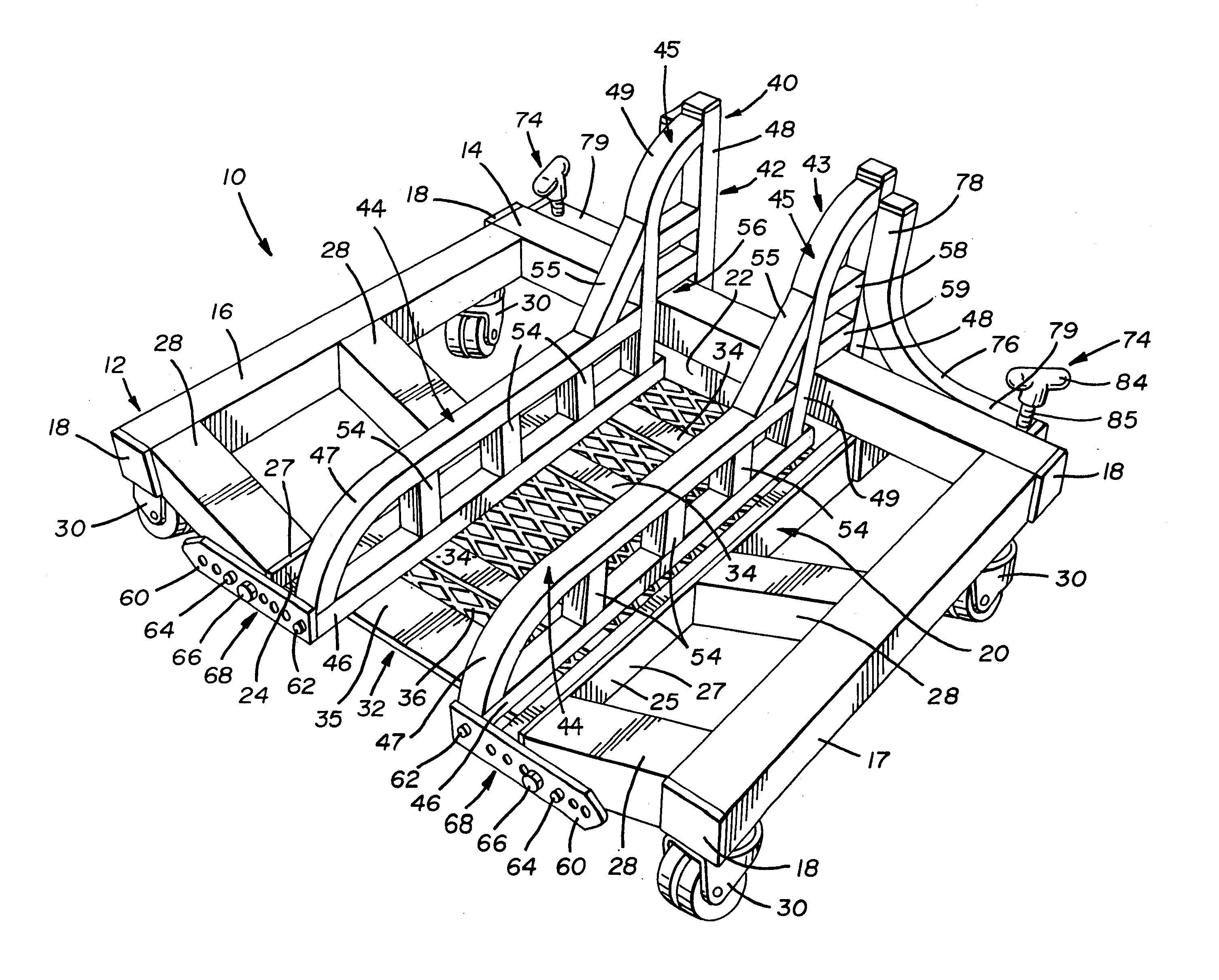
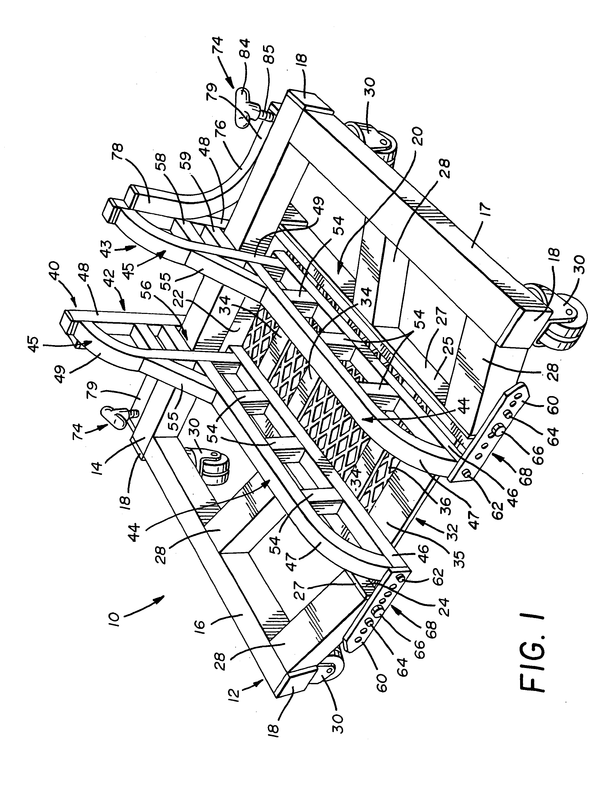
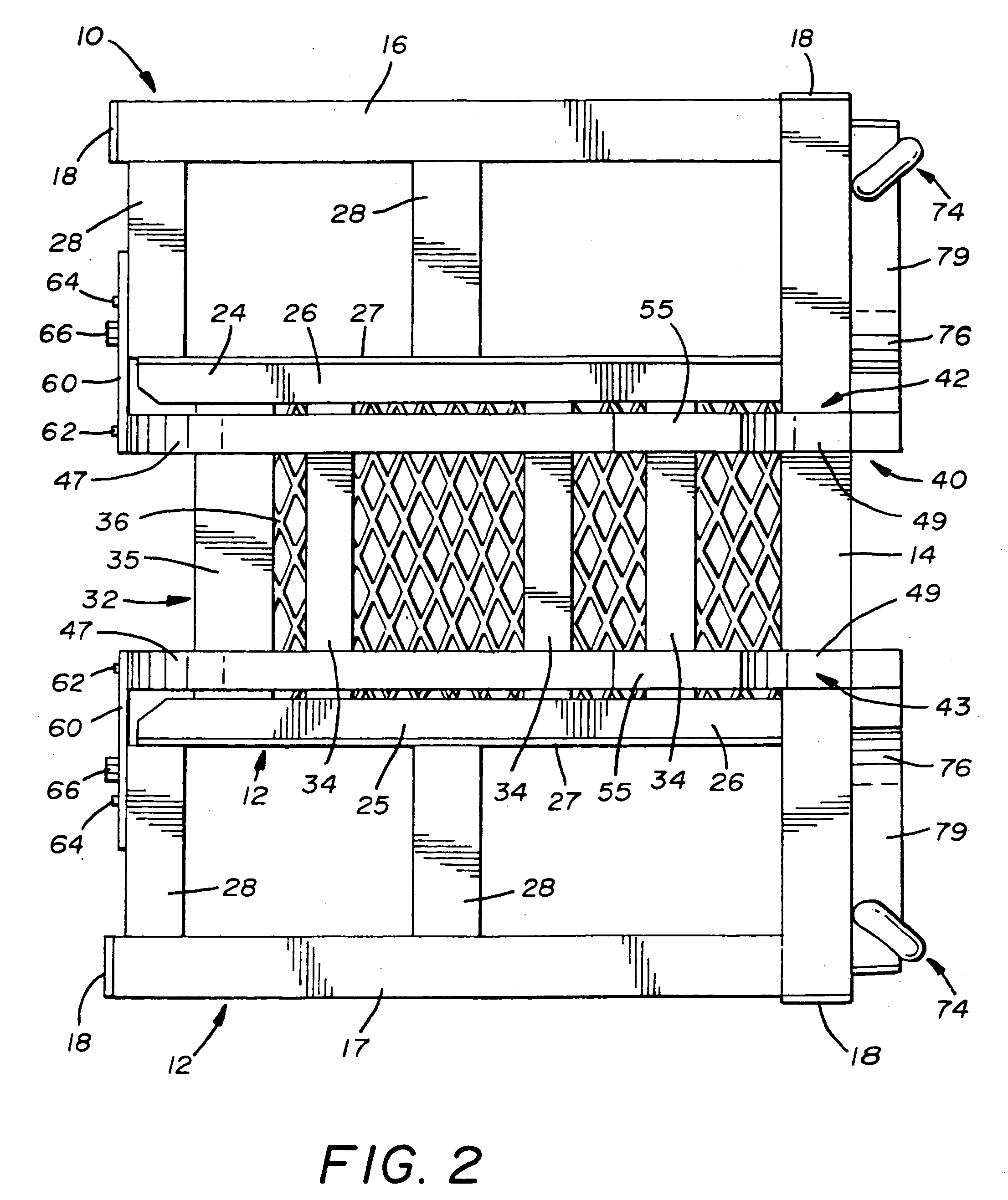
[0014] A motorcycle dolly according to the present invention is generally indicated by the numeral 10 in FIGS. 1-5, and is configured to retain either the front wheel or rear wheel of a motorcycle thereon. The motorcycle dolly 10 is ultimately positioned on the surface of a floor, and includes a frame 12 which can be U-shaped. The frame 12 is formed by a connecting member 14 which spaces a first leg member 16 and a second leg member 17. The connecting member 14, the first leg member 16 and second leg member 17 can be formed from tubular stock material having a square cross-section. As seen in FIGS. 1-4, end caps 18 (ideally constructed of polymeric material) are sized to match the inner cross-sectional dimensions of the connecting member 14, the first leg member 16 and second leg member 17, and are provided to cover the open ends thereof.

[0015] The first leg member 16 and second leg member 17 are substantially parallel to one another, and define a space therebetween for accommodati...


PUM


Abstract

A motorcycle dolly is provided for supporting a front wheel or rear wheel of a motorcycle or other similar two-wheel vehicle on a work surface. The motorcycle dolly includes a frame, a wheel support platform carried by the frame, a plurality of casters attached to the frame, and a first clamping member and a second clamping member pivotably attached to the frame. The wheel support platform selectively receives either the front wheel or rear wheel thereon, and the plurality of casters support the motorcycle dolly for movement on the work surface. The first clamping member and second clamping member can be selectively pivoted with respect to one another to clamp either the front wheel or rear wheel therebetween. As such, when either the front wheel or rear wheel is securely retained between the first clamping member and second clamping member on the motorcycle dolly, the motorcycle can be repositioned using the motorcycle dolly.

Description

CROSS REFERENCE TO RELATED APPLICATION [0001] This application claims the benefit of U.S. Provisional Application Ser. No. 60 / 577,866, filed on Jun. 8, 2004.TECHNICAL FIELD [0002] The present invention relates a motorcycle dolly for supporting either the front wheel or rear wheel of a motorcycle. More particularly, the present invention relates to a motorcycle dolly having a first clamping member and a second clamping member adjustable with respect to one another to retain a motorcycle wheel in position on the motorcycle dolly. More specifically, the present invention relates to a motorcycle dolly having a pivotably adjustable first clamping member, a pivotably adjustable second clamping member, and a wheel support platform, the first clamping member and second clamping member being adjustable to clamp a motorcycle wheel in position on the wheel support platform. BACKGROUND ART [0003] Motorcycles and other two-wheeled vehicles are difficult to store. For example, motorcycles are inh...

Claims


Application Information

Patent Timeline
Patent Type & Authority Applications(United States)
IPC IPC(8): A47F7/00B60S13/00B62B5/00
CPCB60S13/00B62B2202/90B62B5/0083
Inventor JOHNSON, CHARLES RICHARD
Owner JOHNSON CHARLES RICHARD
Why Eureka
Try Eureka