Thermostatic valve for a cooling circuit

a technology of cooling circuit and thermostatic valve, which is applied in the direction of functional valve types, water supply tanks, gas/liquid distribution and storage, etc., can solve the problems of excessive pressure in water cooling circuits, inability to regulate an increase in pressure, and inability to meet the requirements of the valve described in the aforementioned documents

Inactive Publication Date: 2006-01-12
VERNET SA
View PDF2 Cites 15 Cited by
  • Summary
  • Abstract
  • Description
  • Claims
  • Application Information

AI Technical Summary

Benefits of technology

[0007] For this purpose, the invention relates to a thermostatic valve for a cooling circuit, in particular associated with a heat engine, comprising a main housing which forms an inlet orifice for a fluid and at least one outlet orifice for this fluid, a check mechanism that is movable relative to the housing and is suitable for regulating the passage of the fluid between the inlet orifice and the outlet orifice, a seat, which is stationary relative to the housing, for receiving the check mechanism, and a thermostatic element that is provided with a body, which contains an expandable material, and with a piston that is movable relative to the body, this body being stationary relative to the housing. The valve according to the invention comprises further a connecting piece between the check mechanism and the piston, which connecting piece is integral with the check mechanism and delimits a blind recess for receiving the piston, the base of the recess forming a stop for the piston when the difference in pressure on either side of the check mechanism is less than a predetermined value, thus connecting the check mechanism and the piston to each other kinematically, while the wall of the recess forms a surface for sliding contact with the piston when this difference in pressure is greater than said predetermined value, thus allowing the check mechanism to be displaced relative to the piston, in the displacement direction of the piston.

Problems solved by technology

Some operating conditions of heat engines may cause excessive pressure in the water cooling circuits, whilst the thermostatic valve is not opened by thermal stresses as the temperatures are too low.
This excessive pressure may be harmful to some components of the circuit.
The valves described in the aforementioned documents do not, on the other hand, have any facilities for regulating an increase in pressure of the fluid around the thermostatic element.

Method used


Image

  • Thermostatic valve for a cooling circuit
  • Thermostatic valve for a cooling circuit
  • Thermostatic valve for a cooling circuit

Examples


Embodiment Construction

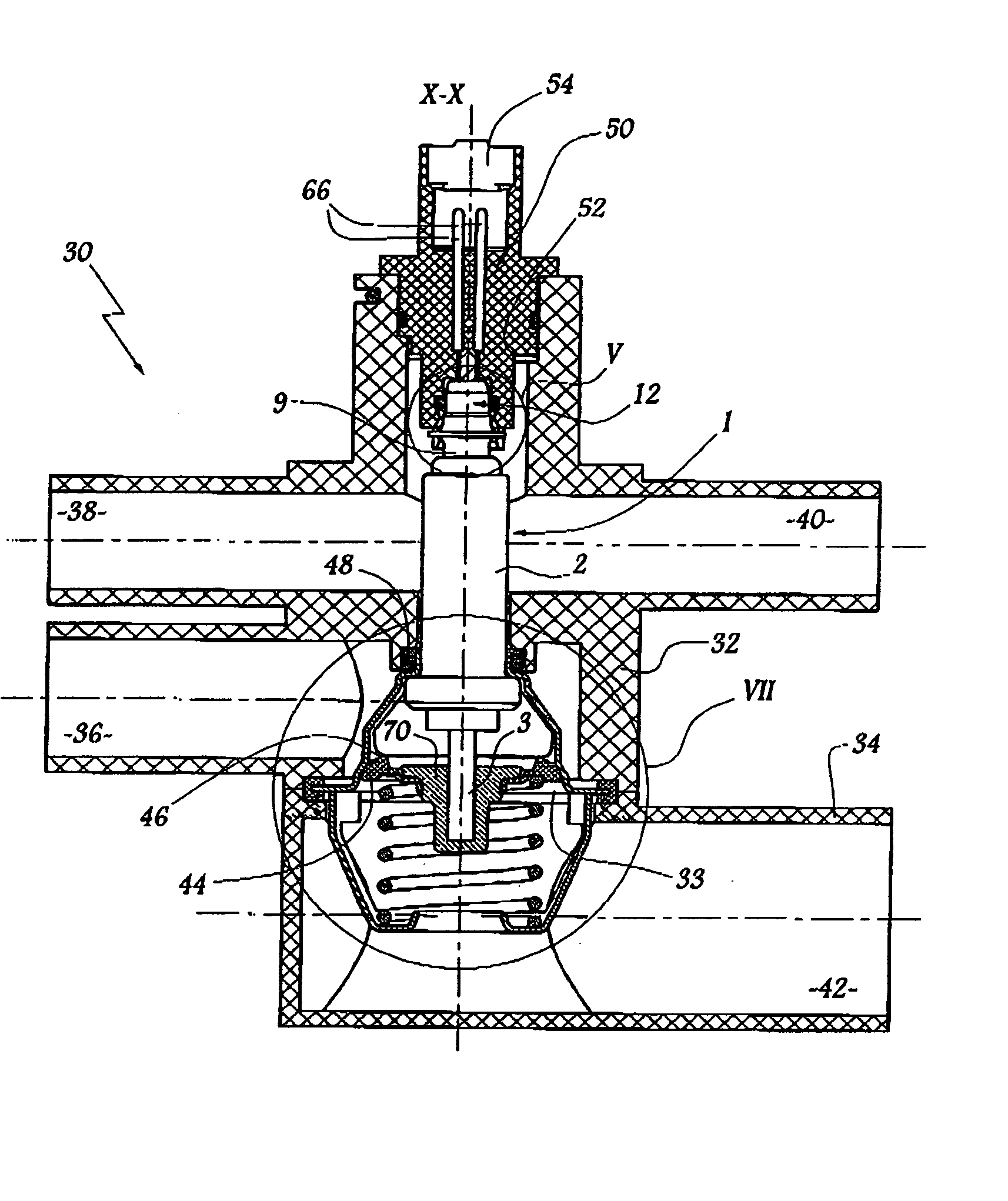
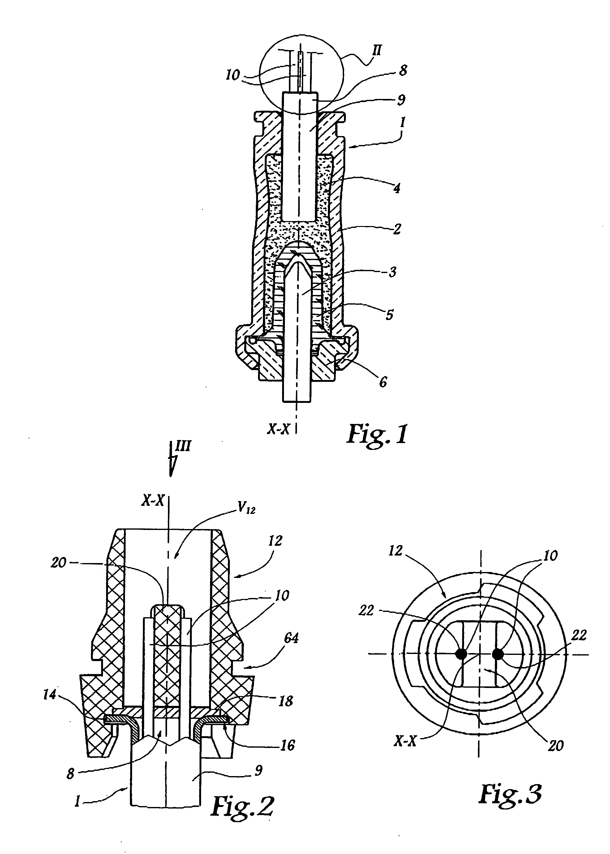
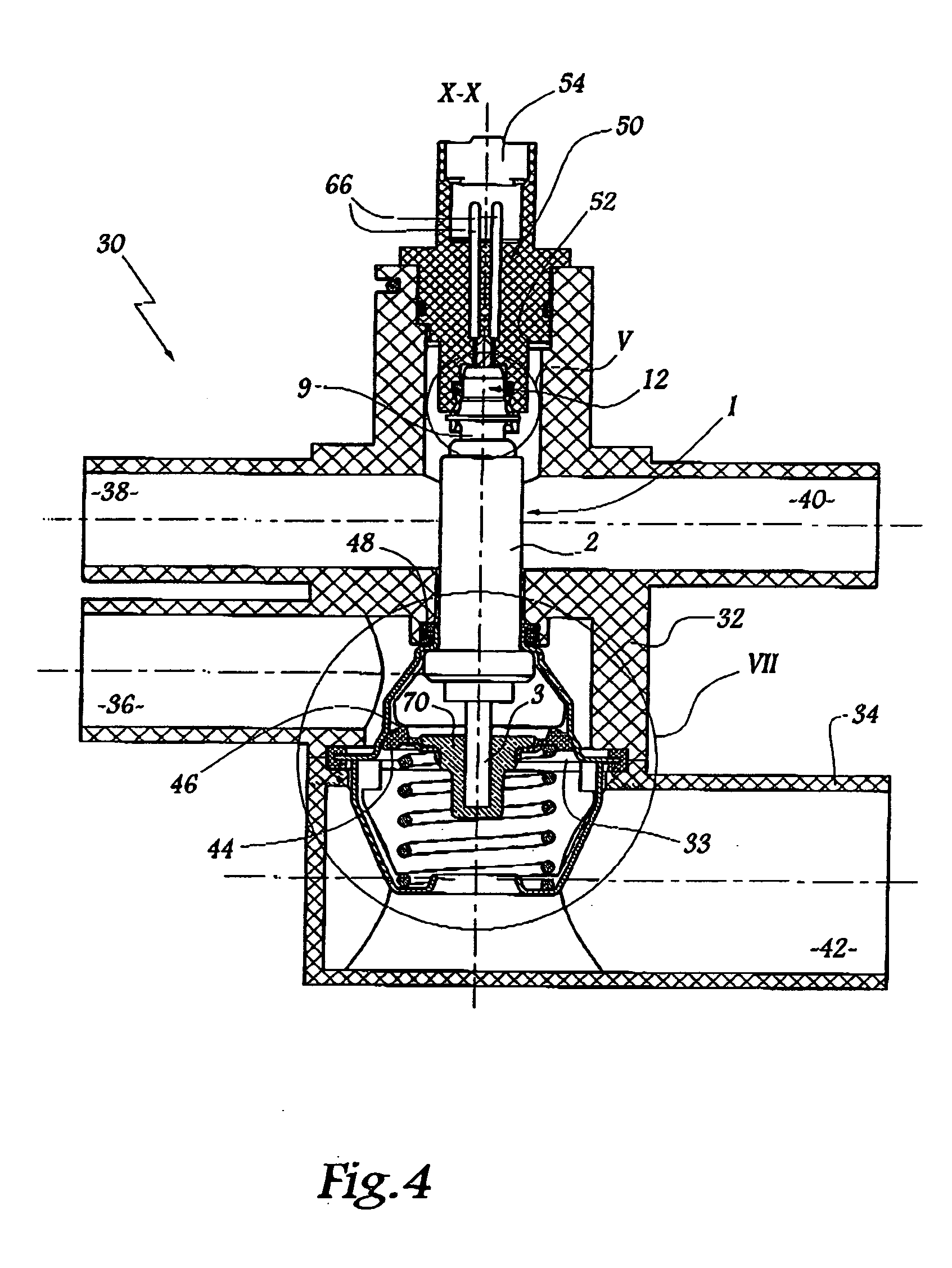
[0032]FIG. 1 shows a known thermostatic element, which has the reference numeral 1 and is intended to be immersed into a fluid of variable temperature.

[0033] The thermostatic element 1 substantially comprises a body 2, which is made of a readily heat-conducting material, such as a metallic material, for example, and a piston 3, in the form of a rod that is movable relative to the body 2. The body 2 delimits on the inside an expandable-type reception cavity 4, which is generally made of wax and is tightly confined by an elastomer membrane 5, which is held firmly relative to the body 2 by a lid 6.

[0034] When the temperature of the fluid in which the thermostatic element 1 is immersed increases, the expansion of the wax 4 causes the piston 3 to be pulled in the longitudinal direction X-X of the thermostatic element. When the wax contracts, returning means (not shown) are generally provided in order to bring the piston 3 back inside the body 2.

[0035] Electrical heating means 8 are pr...


PUM


Abstract

This valve comprises a housing, a movable check mechanism that is suitable for regulating the passage of a fluid between an inlet orifice and an outlet orifice of the housing, a stationary seat for receiving the valve, and a thermostatic element that is provided with a body, which contains an expandable material, and a movable piston, this body being stationary relative to the housing. In order to prevent excessive pressure from being generated in the valve, on the side of the check mechanism where the thermostatic element is arranged, the check mechanism and the piston are connected by a part that is integral with the valve and delimits a blind recess for receiving the piston, the base of the recess forming a stop for the piston when the difference in pressure on either side of the check mechanism is less than a predetermined value, while the wall of the recess forms a surface for sliding contact with the piston when this difference in pressure is greater than this predetermined value.

Description

TECHNICAL FIELD [0001] The present invention relates to a thermostatic valve comprising an expandable-material thermostatic element that is suitable for controlling the movements of a check mechanism for regulating the passage of a fluid through the valve. BACKGROUND TO THE INVENTION [0002] In numerous applications in the field of fluids, in particular for cooling heat engines, valves of this type are used for distributing a fluid entering various tracts as a function of the characteristics, in particular the temperature characteristics, of this entering fluid. [0003] In currently used valves, the free end of the piston of the thermostatic element is often rigidly connected to the check mechanism regulating the flow of the fluid into the valve, such that the distance of the valve from its seat is controlled by the development of the temperature of the fluid in which the thermostatic element is immersed. [0004] Some operating conditions of heat engines may cause excessive pressure in...

Claims


Application Information

Patent Timeline
Patent Type & Authority Applications(United States)
IPC IPC(8): G05D23/00
CPCG05D23/2752G05D23/023G05D23/1921G05D23/275Y10T137/86364Y10T137/877
Inventor ROMAN, JEAN-MICHELMABBOUX, LIONEL
Owner VERNET SA
Why Eureka
Try Eureka