Blind fastener satellite dish mounting device

a satellite dish and blind fastener technology, applied in the direction of machine supports, building scaffolds, other domestic objects, etc., can solve the problems of similar damage to the shingled roof covering or wall siding

Inactive Publication Date: 2006-01-26
CAPOZZI STEPHEN J +2
View PDF24 Cites 22 Cited by
  • Summary
  • Abstract
  • Description
  • Claims
  • Application Information

AI Technical Summary

Problems solved by technology

One reason for this reluctance is the concern that visible holes, or similar damage to the shingled roof covering or wall siding, would result, should the homeowner decide to relocate or even remove the mounting device for the satellite dish.

Method used


Image

  • Blind fastener satellite dish mounting device
  • Blind fastener satellite dish mounting device
  • Blind fastener satellite dish mounting device

Examples


Embodiment Construction

Nomenclature

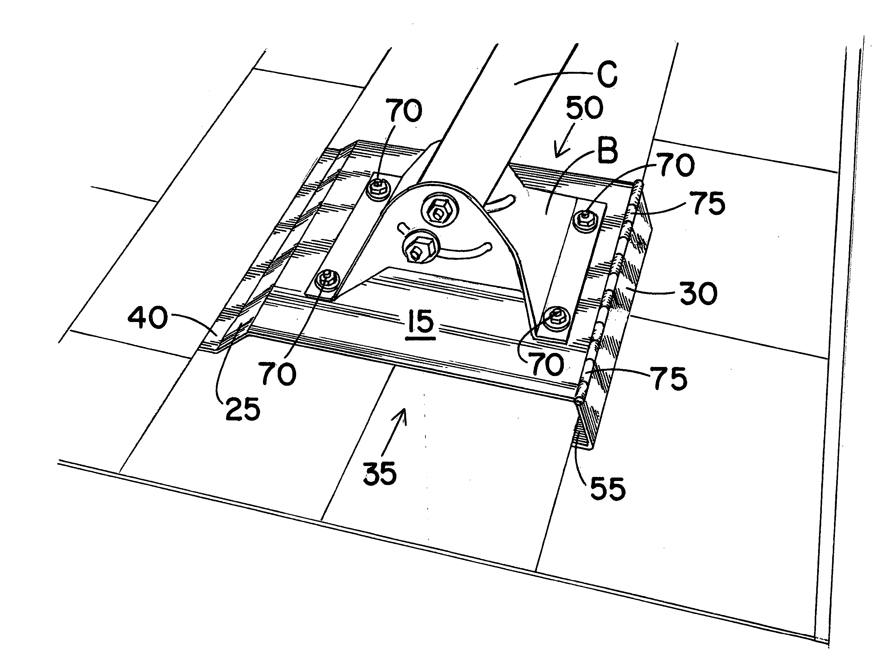
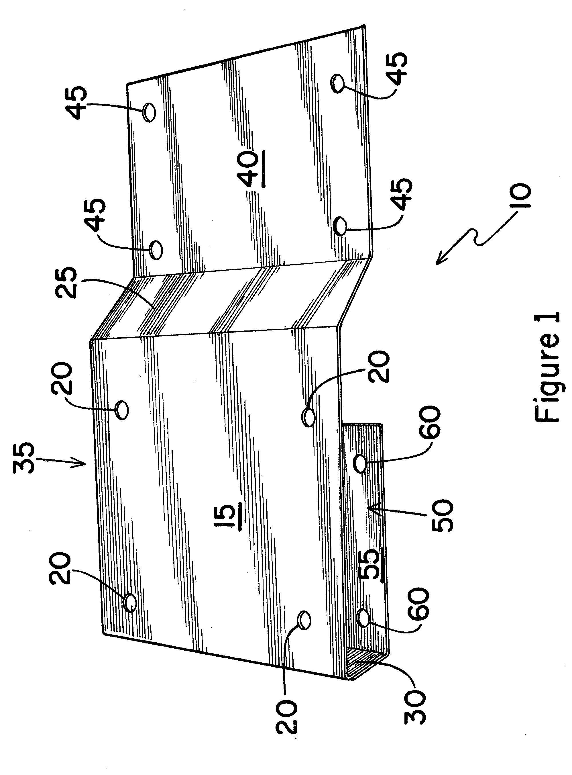
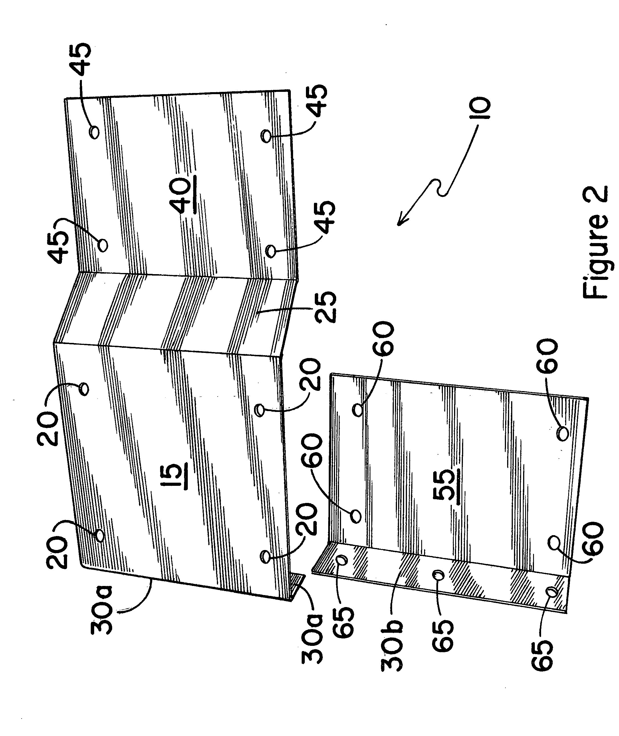
[0039]10 Base Mounting Device

[0040]15 Planar Elevated Platform Section

[0041]20 Apertures in Platform Section

[0042]25 First Sidewall of Platform Section

[0043]30 Second Sidewall of Platform Section

[0044]30a Upper Sidewall Section

[0045]30b Lower Sidewall Section

[0046]35 First Open Side of Platform Section

[0047]40 Planar Outer Mounting Tab

[0048]45 Apertures in Outer Mounting Tab

[0049]50 Second Open Side of Platform Section

[0050]55 Planar Inner Mounting Tab

[0051]60 Apertures in Inner Mounting Tab

[0052]65 Apertures in Overlapping Sidewall Section of Second Sidewall

[0053]70 Threaded Fasteners

[0054]75 Hinge Member Attached to Second Sidewall

[0055] B Base of Satellite Dish Mount

[0056] C Pipe of Satellite Dish Mount

Construction

[0057] The invention is a base mounting device adapted for receiving and securing the mounting base of a satellite dish to a roof or sidewall structure. The device comprises an elevated platform section with a plurality of apertures the...


PUM


Abstract

A device for mounting the base of a satellite dish is disclosed. The base mounting device is secured to a shingled roof or sidewall structure with little or no disruption to the integrity of the shingled roof or sidewall. The mounting device provides an extremely stable structure suitable for securing a mounting base of a satellite dish mounting unit. The base mounting device is readily moved from one location to another, or completely removed from the roof or sidewall structure with minimal impact on the integrity of the shingled roof or sidewall covering.

Description

CROSS-REFERENCE TO RELATED APPLICATIONS, IF ANY [0001] This application claims the benefit under 35 U.S.C. §119 (e) of co-pending provisional application Ser. No. 60 / 590,897, filed 23 Jul. 2004. Application Ser. No. 60 / 590,897 is hereby incorporated by reference.STATEMENT REGARDING FEDERALLY SPONSORED RESEARCH OR DEVELOPMENT [0002] Not applicable. REFERENCE TO A MICROFICHE APPENDIX, IF ANY [0003] Not applicable. BACKGROUND OF THE INVENTION [0004] 1. Field of the Invention [0005] The present invention relates to a bracket device for mounting a satellite dish and, more particularly, to a base mounting bracket device for mounting a satellite dish to a roof structure, and most particularly, to a base mounting bracket device secured to a roof or sidewall structure without producing visible holes in the roof shingles or the wall siding of a structure. [0006] 2. Background Information [0007] With the recent increase in popularity of high speed digital communications, an ever increasing nee...

Claims


Application Information

Patent Timeline
Patent Type & Authority Applications(United States)
IPC IPC(8): E04G3/00
CPCH01Q1/1221
Inventor CAPOZZI, STEPHEN J.DICKERSON, RONALD W.BOWE, DARIN
Owner CAPOZZI STEPHEN J
Why Eureka
Try Eureka