Structure of stepper

a stepper and body technology, applied in the field of steppers, can solve the problems of limited exercised body parts, less effective, and inconvenient use of the structure of the conventional stepper

Inactive Publication Date: 2006-01-26
ZENG CIAN CHANG
View PDF7 Cites 19 Cited by
  • Summary
  • Abstract
  • Description
  • Claims
  • Application Information

AI Technical Summary

Benefits of technology

[0011] 2. With this special new design, when the pedals are stepped down, they generate the motion that not only moves up and down,

Problems solved by technology

However, problems are present in the structure of the conventional stepper in usage.
When the stepper moves, its left and right pedals move repeatedly in a simple up and down motion, even though it can achieve the purpose of exercising, as a result of

Method used


Image

  • Structure of stepper
  • Structure of stepper
  • Structure of stepper

Examples


Embodiment Construction

[0022] The features and the advantages of the present invention will be more readily understood upon a thoughtful deliberation of the following detailed description of a preferred embodiment of the present invention with reference to the accompanying drawings.

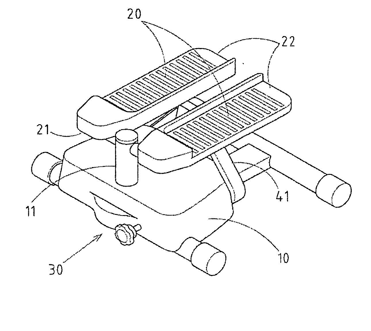
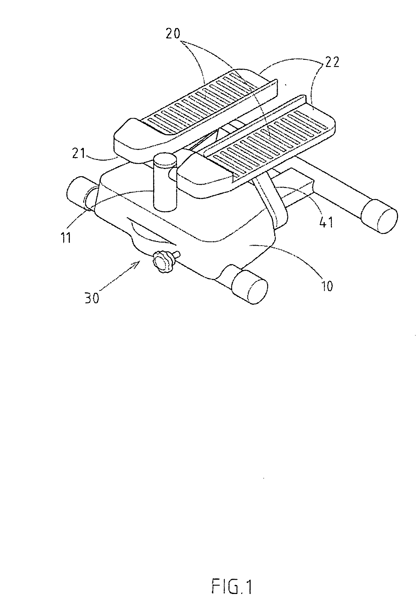
[0023] As shown in FIGS. 1-5, a stepper with improved structure embodied in the present invention comprises:

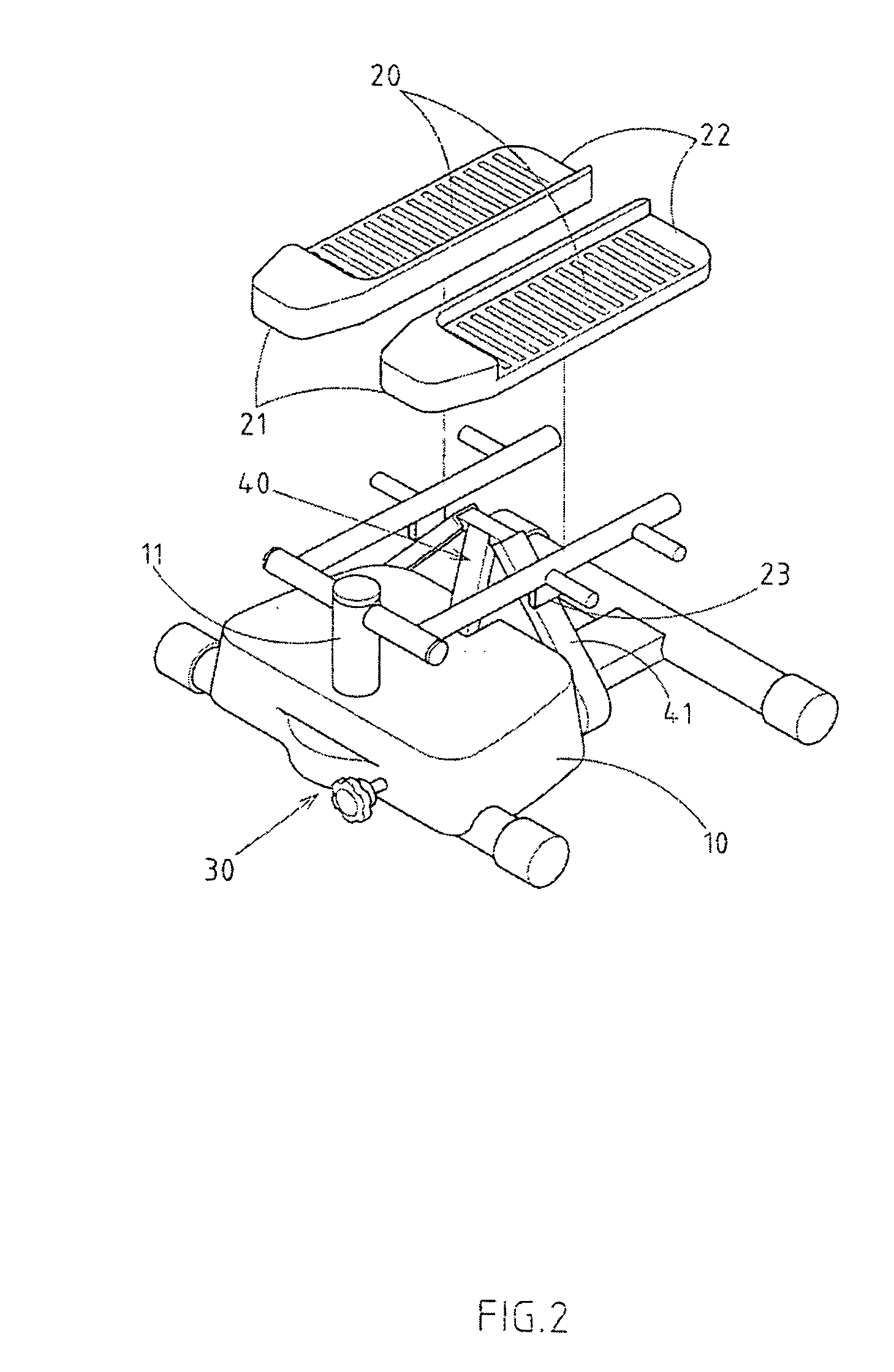
[0024] a base 10, two pedals 20 and the resistance device 30; whereas the front ends 21 of these two pedals 20 are pivoted respectively on the protruding prop 11 at the front of the base 10, which becomes the movable ends 22 for the two pedals 20 that provides the twisting motion in up and down directions, and forms a force of resistance when stepping provided by the resistance device 30; the features lie in:

[0025] the bottom of the protruding prop 11 is mounted on the base 10 pivotally, which puts the prop 11 in a revolvable position;

[0026] a triangular guide 40 mounted on the base 10, and its two oblique planes 41 s...


PUM


Abstract

The stepper with improved structure has a base, two pedals and the resistance device. The front ends of these two pedals are pivoted respectively on the protruding prop at the front of the base, which becomes the movable ends for the two pedals that provides the twisting motion in up and down directions, and forms a force of resistance when stepping provided by the resistance device. The bottom of the protruding prop is mounted on the base pivotally, which puts the prop in a revolvable position; a triangular guide mounted on the base, and its two oblique planes sets correspondingly and relatively to the movable ends of the two pedals, and on the bottoms of the movable ends of the pedals are the sliding part that are mounted pivotally on the oblique planes of the triangular guides. When the pedals are stepped down, they generate the motion that twists left and right downward diagonally as well.

Description

RELATED U.S. APPLICATIONS [0001] Not applicable. STATEMENT REGARDING FEDERALLY SPONSORED RESEARCH OR DEVELOPMENT [0002] Not applicable. REFERENCE TO MICROFICHE APPENDIX [0003] Not applicable. FIELD OF THE INVENTION [0004] The present invention relates generally to a stepper, and more particularly to a stepper that generates twisting motion that moves downward diagonally when the pedals are stepped down. BACKGROUND OF THE INVENTION [0005] The structure for the conventional stepper comprises right and left pedals that are pivoted on the base, and the front ends of the left and right pedals are pivoted on the lateral bar, which makes the ends of the pedals twist with the lateral bar, and coordinates with the resistance pressure bar on the bottom. By this structure, the users can step on its right and left pedals with both feet to make the stepping motion. However, problems are present in the structure of the conventional stepper in usage. [0006] When the stepper moves, its left and rig...

Claims


Application Information

Patent Timeline
IPC IPC(8): A63B22/04A63B22/18A63B23/04
CPCA63B2208/0204A63B22/0064
Inventor ZENG, CIAN-CHANG
Owner ZENG CIAN CHANG
Why Eureka
Try Eureka