Phone plug structure with a locking function

a technology of phone plugs and functions, applied in the direction of coupling devices, two-part coupling devices, electrical devices, etc., can solve the problems of easy theft of electronic devices and lack of locking functions of phone plugs

Inactive Publication Date: 2006-02-02
LIAO SHENG HSIN
View PDF5 Cites 14 Cited by
  • Summary
  • Abstract
  • Description
  • Claims
  • Application Information

AI Technical Summary

Problems solved by technology

Hence it is easy for anyone to separate the phone plug and the socket 30a, so the electronic apparatus is easily stolen.
It is obvious that the phone plug lacks a locking function.

Method used


Image

  • Phone plug structure with a locking function
  • Phone plug structure with a locking function
  • Phone plug structure with a locking function

Examples


Embodiment Construction

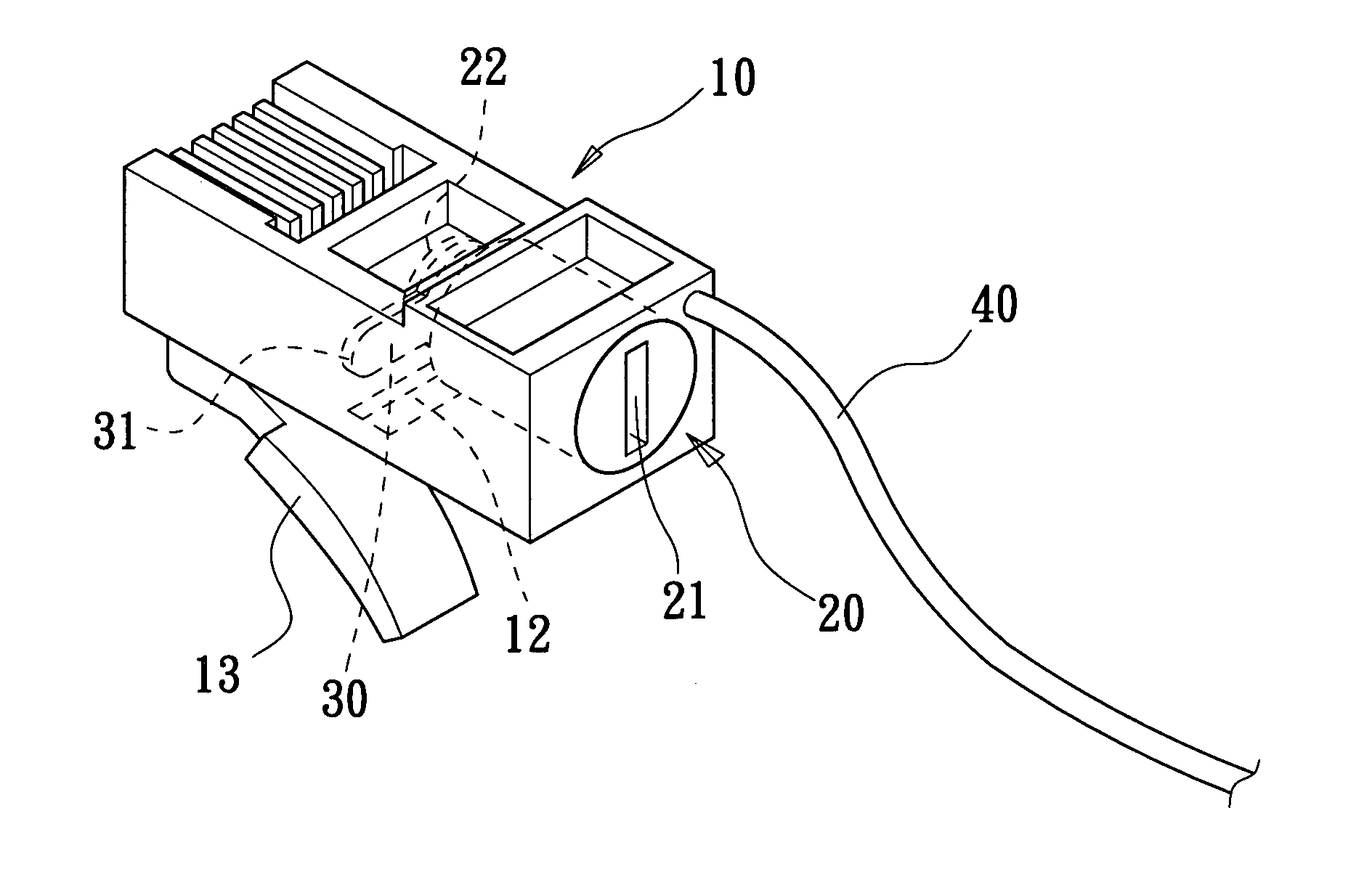
[0027] Referring to FIGS. 3 and 4, the present invention provides a phone plug structure with a locking function. The phone plug structure includes an insulative housing 10, a locking device 20, an interfered element 30 and an extension wire 40. The insulative housing 10 is made of insulating materials, such as plastic. The shape of the insulative housing 10 is approximately the same as the conventional insulative housing of the phone plug. The insulative housing 10 has a receiving space 11 formed therein for receiving the locking device 20. The insulative housing 10 further has a through hole 12 formed therein. The through hole 12 communicates with the receiving space 11. The through hole 12 is extended to an outer wall of the insulative housing 10. The insulative housing 10 has a retaining element 13 with a retaining function disposed on an outside thereof. The retaining element 13 has a predetermined length, so the retaining element has an elastic function.

[0028] The locking dev...


PUM


Abstract

A phone plug structure with a locking function includes an insulative housing, a locking device, an interfered element and an extended wire. The insulative housing has a receiving space formed therein, and a retaining element disposed on an outside thereof. The locking device is received in the insulative housing. The interfered element connects with the locking device, wherein the interfered element is rotated and projected outside the insulative housing by the locking device to contact against the retaining element. The extended wire has one end connecting to the insulative housing. Whereby the phone plug structure has a locking device combined therein, so that the phone plug structure can not only transmit signal to an electronic apparatus, but can also be locked without needing another locking device.

Description

BACKGROUND OF THE INVENTION [0001] 1. Field of the Invention [0002] The present invention relates to a phone plug structure with a locking function, and particularly relates to a phone plug structure having a lock combined therein. [0003] 2. Description of the Related Art [0004] Referring to FIG. 1, a phone plug connects with a plurality of signal wires. The phone plug can be used to electrically connect between the signal wires and an electronic apparatus such as a computer. The phone plug has a casing 10a, a retaining element 11a with a retaining function disposed on an outside of the casing 10a, and a plurality of terminals 12a disposed inside the casing 10a. The terminals 12a can be moved a short distance longitudinally. A communication wire 20a is inserted into the casing 10a from a rear side of the casing 10a. The terminals 12a pierce into the communication wire 20a to electrically connect the terminals 12a and the communication wire 20a. [0005] The phone plug can be inserted ...

Claims


Application Information

Patent Timeline
Patent Type & Authority Applications(United States)
IPC IPC(8): H01R13/625H01R13/627H01R24/58
CPCH01R24/62H01R13/6272
Inventor LIAO, SHENG-HSIN
Owner LIAO SHENG HSIN
Why Eureka
Try Eureka