Multi-port cabling system and method

a multi-port cabling and multi-port technology, applied in the direction of electrical equipment, connection, coupling device connection, etc., can solve the problems of affecting the installation efficiency so as to facilitate the wall-mounting of the cabling system, increase or decrease the number of installed ports, and facilitate the effect of easy and rapid deploymen

Active Publication Date: 2006-02-02
AMERICA POWER CONVERSION CORP
View PDF44 Cites 56 Cited by
  • Summary
  • Abstract
  • Description
  • Claims
  • Application Information

AI Technical Summary

Benefits of technology

[0013] Various aspects of the invention may provide one or more of the following capabilities. Cable installation to equipment racks and rack enclosures can be organized such that the number of cables needed to meet service requirements is reduced. A reduced number of cables requires fewer components for installation and management and thereby can help to reduce the need for cable trays and wire management components and hardware. As a result, cable installation can be faster with reduced labor, which often translates into lower installation costs. In addition, a reduced number of cables can help to reduce or eliminate disturbance to active equipment operating in an equipment room or data center during installation. The reduced number of cables can help to minimize the amount of intra-rack and inter-rack space required for cabling and cable management. Further, the reduced number of cables helps to decrease the diameter of, for instance, a cable bundle such that cables can be easily routed in a rack or a cable tray.
[0023] A plurality of connector heads can provide scalability and flexibility for future expansion by enabling a plurality of ports to be readily deployed within racks or enclosures such that spare ports are available with reduced installation effort and at reduced cost. In addition, an expandable design provided by a plurality of connector heads of the cabling system can reduce downtime of equipment and data centers during reconfiguration and expansion.

Problems solved by technology

Configuration of equipment rooms and data and network centers to create effective IT environments presents a number of challenges.
Such patch panels can have a massive number of cables such that installing and managing these cables is a significant task.
Wire termination to punch down blocks requires a technician and is time-consuming, often contributing substantially to installation costs.
Patch panel cable installations are typically considered “built-in” and are essentially permanent configurations as relocating such installations, for instance, during reconfiguration of racks or equipment rooms is often inconvenient and difficult.
Excessive bending and kinking can cause permanent damage that adversely affects cable performance.

Method used


Image

  • Multi-port cabling system and method
  • Multi-port cabling system and method
  • Multi-port cabling system and method

Examples


Embodiment Construction

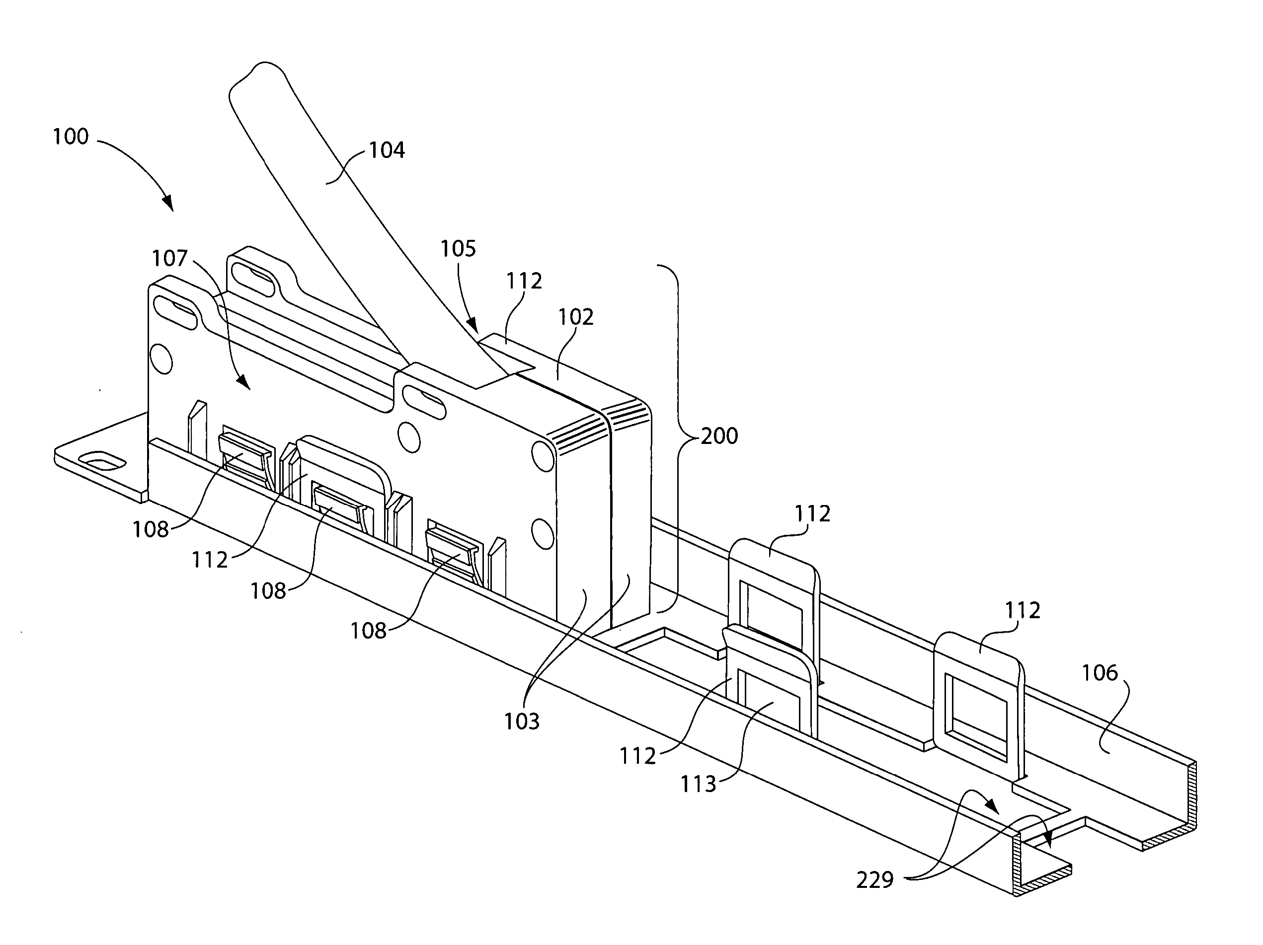
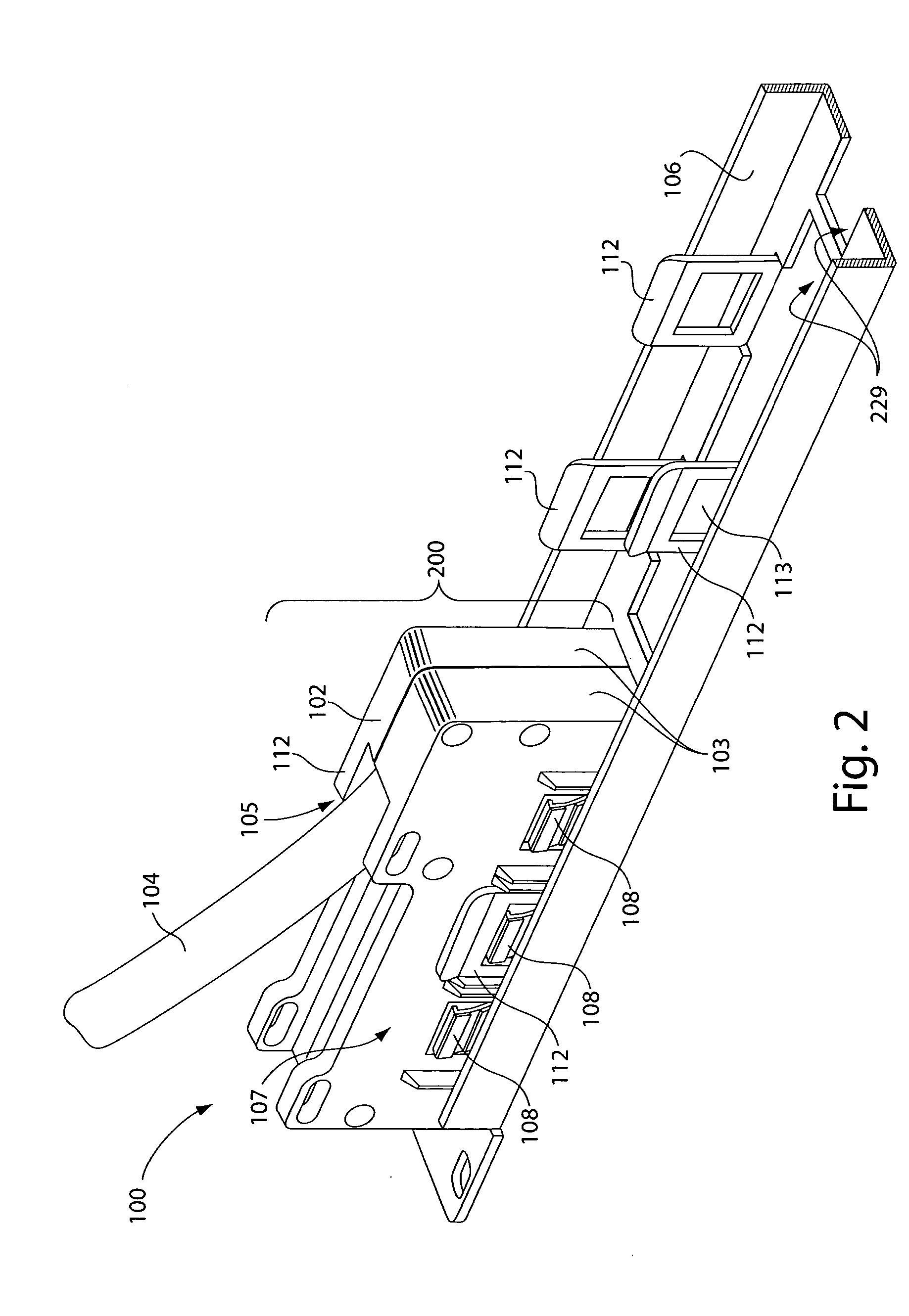
[0051] The invention provides a cabling system configured for use in rack enclosures and open-frame racks employed in server, telecommunications and networking applications to configure IT environments of equipment rooms, data centers and networking centers. The cabling system according to the invention is configured to be rack-mounted and to provide tool-less installation. The cabling system provides preterminated and pretested wiring to eliminate on-site wire termination and testing during installation and / or during expansion of equipment racks and equipment rooms and data centers. The cabling system includes a rack-mountable cabling assembly including a single unit connector head that receives and terminates at least one cable. The connector head comprises a plurality of ports. Each port is configured to accept connective wiring of individual rack-mounted equipment components to adapt each equipment component to propagate signals through the cable to the port. The connector head ...


PUM

PropertyMeasurementUnit
angleaaaaaaaaaa
height H2aaaaaaaaaa
areaaaaaaaaaaa

Abstract

A multi-port cabling system for use in installing cable to an equipment rack or enclosure or within an equipment room or data center includes a cabling assembly comprising at least one connector head having a plurality of ports and at least one cable operatively connected to the plurality of ports. The at least one cable terminates internally within the connector head to operatively couple the cable to the plurality of ports. The system further includes a mounting bracket. The mounting bracket and the connector head are each configured for tool-less attachment of one or more cabling assemblies to the bracket. The mounting bracket is further configured to removably mount to an equipment rack or enclosure, and / or to a wall, to thereby install one or more cables. The cabling assembly and the cabling system help to eliminate on-site cable termination and testing during installation of cables to rack-mounted equipment.

Description

FIELD OF THE INVENTION [0001] The invention relates to cable installation and management in an equipment rack or enclosure. BACKGROUND OF THE INVENTION [0002] Configuration of equipment rooms and data and network centers to create effective IT environments presents a number of challenges. Integration of servers, networking equipment and storage devices, for instance, requires careful planning to configure an environment that can address current as well as future and varying requirements. Such requirements can include signal speeds, power densities, cooling and flexibility with respect to rack equipment architecture. Ideal solutions to meet such requirements are quick and easy to install such that new configurations, equipment, and systems can be deployed with minimal equipment downtime and without substantial cost. [0003] Cable management systems, equipment and techniques used to configure racks and to provide service connections to rack-mounted equipment and to provide inter-rack c...

Claims


Application Information

Patent Timeline
Patent Type & Authority Applications(United States)
IPC IPC(8): H01R13/60
CPCH01R13/741H01R25/003H04Q1/141Y10T29/49208H04Q1/021H04Q1/13H04Q2201/02
Inventor SPITAELS, JAMES S.BRYAN, DANIEL
Owner AMERICA POWER CONVERSION CORP
Why Eureka
Try Eureka